EasyManua.ls Logo

Maxim Integrated MAX32664 - MAX32664 I2 C Message Protocol

Default Icon
52 pages
Print Icon
To Next Page IconTo Next Page
To Previous Page IconTo Previous Page
Loading...
Maxim Integrated Page 19 of 52
MAX32664 I
2
C Message Protocol Definition
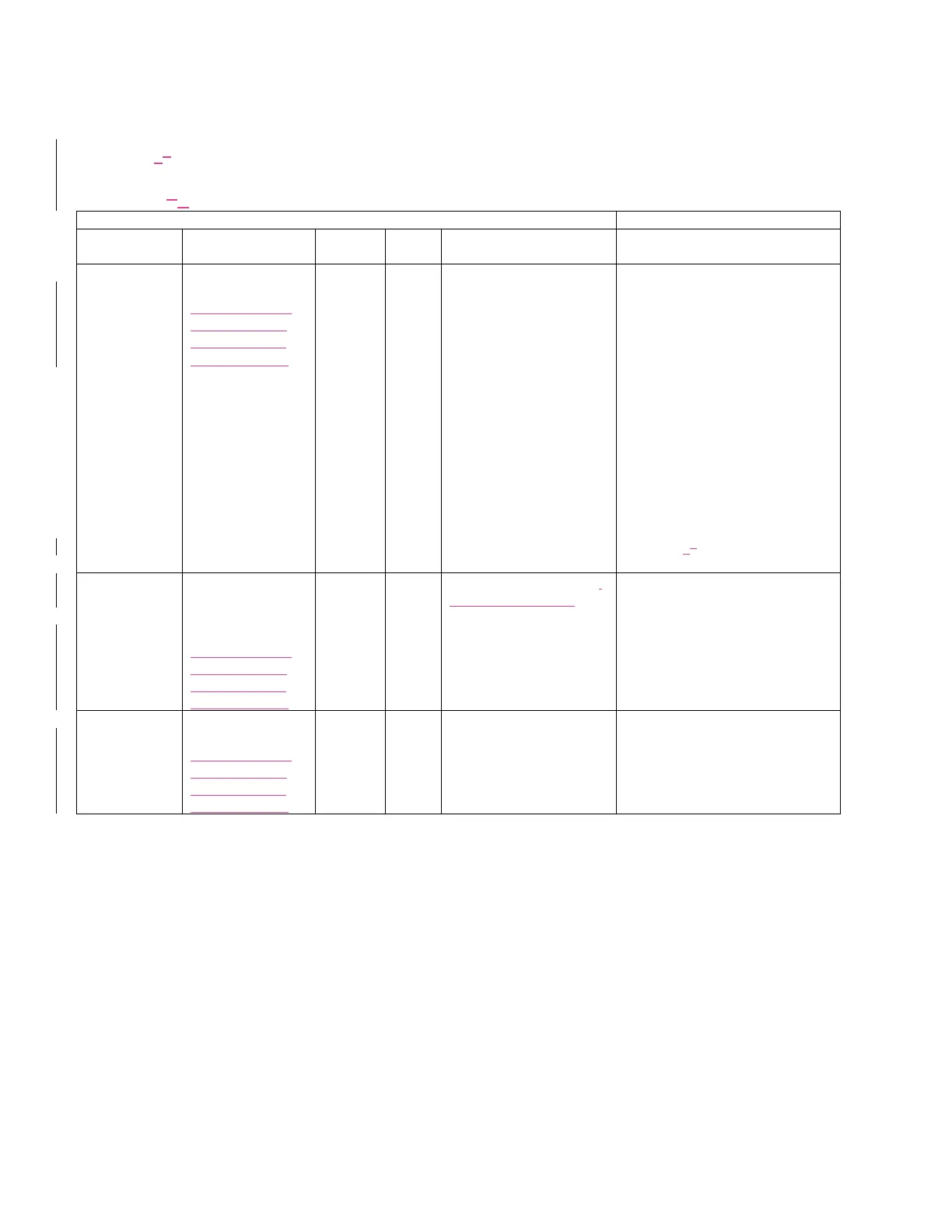
Table 65 defines the I
2
C message protocol for the MAX32664.
Table 56. MAX32664 I
2
C Message Protocol Definitions
HOST COMMAND
MAX32664
FAMILY NAME
DESCRIPTION
FAMILY
BYTE
INDEX
BYTE
WRITE BYTES
RESPONSE BYTES
Read Sensor
Hub Status
Read sensor hub
status
(MAX32664GWEA,
MAX32664GWEB,
MAX32664GWEC,
MAX32664GWED)
0x00
0x00
-
Err0[0]: 0 = No Error; 1 = Sensor
Communication Problem
Err1[0]: Not used
Err2[0]: Not used
DataRdyInt[3]: 0 = FIFO below
threshold; 1 = FIFO filled to threshold
or above.
FifoOutOvrInt[4]: 0 = No FIFO
overflow; 1 = Sensor Hub Output FIFO
overflowed, data lost.
FifoInOvrInt[5]: 0 = No FIFO overflow;
1 = Sensor Hub Input FIFO overflowed,
data lost.
DevBusy[6]: 0 = Sensor Hub ready; 1 =
Sensor Hub is busy processing.
See Table 76 for the for the bit field
table.
Device Mode
Select the device
operating mode.
The application must
implement this.
(MAX32664GWEA,
MAX32664GWEB,
MAX32664GWEC,
MAX32664GWED)
0x01
0x00
0x00: Exit bootloader mode,
Enter application mode.
0x02: Reset.
0x08: Enter bootloader
mode.
-
Device Mode
Read the device
operating mode.
(MAX32664GWEA,
MAX32664GWEB,
MAX32664GWEC,
MAX32664GWED)
0x02
0x00
-
0x00: Application operating mode.
0x08: Bootloader operating mode.

Table of Contents