EasyManua.ls Logo

Maxim Integrated MAX32664 - MAX32664 Boot Modes; MAX32664 Bootloader Mode; MAX32664 Application Mode

Default Icon
52 pages
Print Icon
To Next Page IconTo Next Page
To Previous Page IconTo Previous Page
Loading...
Maxim Integrated Page 13 of 52
Table 3. Additional GPIOs Used on the MAX32664 for the MAXREFDES220#
MAX32664
DESCRIPTION
DIRECTION FROM THE MAX32664 SIDE
GPIO P0.6
KX122 ACCEL Interrupt
Input
GPIO P0.7
MAX30101 Interrupt
Input
GPIO P0.8
MAX30101, KX122 I2C1_SCL
Output
GPIO P0.9
MAX30101, KX122 I2C1_SDA
Input/Output
Table 4. Additional GPIOs Used on the MAX32664 for the MAXREFDES101#
MAX32664
DESCRIPTION
DIRECTION FROM THE MAX32664 SIDE
GPIO P0.0
KX122 ACCEL Select
Output
GPIO P0.4
SPI MISO: MAX86141, KX122
Input
GPIO P0.5
SPI MOSI: MAX86141, KX122
Output
GPIO P0.6
SPI CLK: MAX86141, KX122
Output
GPIO P0.7
MAX86141 Select
Output
GPIO P0.8
MAX86141 Interrupt
Input
GPIO P0.9
KX122 Interrupt
Input
MAX32664 Bootup and Application Mode
The MAX32664 is programmed to enter either bootloader mode or application mode at the start-up based
on the state of the MFIO pin.
Variations of the MAX32664 part are pre-programmed with the different algorithms and application
firmware. Check with your Maxim representative.
MAX32664 Bootloader Mode
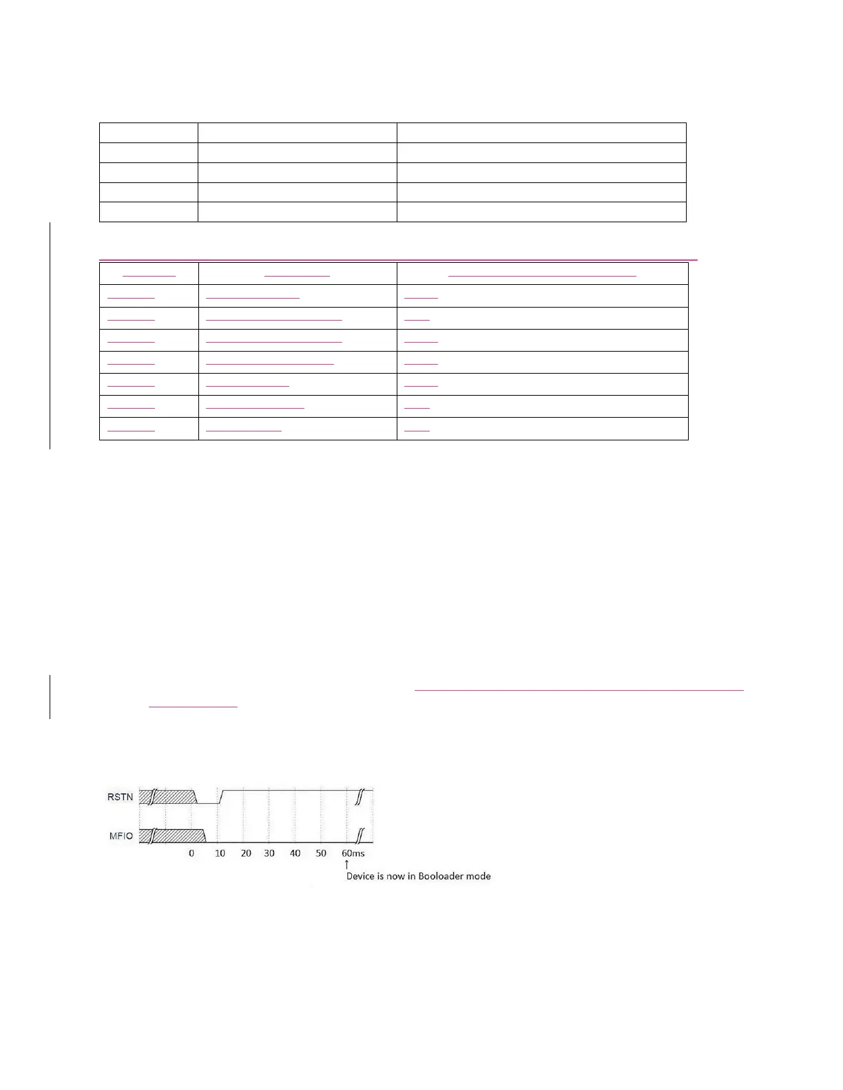
The MAX32664 enters bootloader mode based on the sequencing of the RSTN pin and the MFIO pin. The
necessary sequence is as follows:
Set the RSTN pin low for 10ms.
While RSTN is low, set the MFIO pin to low (MFIO pin should be set low at least 1ms before RSTN
pin is set high).
After the 10ms has elapsed, set the RSTN pin high.
After an additional 50ms has elapsed, the MAX32664 is in bootloader mode.
Figure 4. Entering bootloader mode using the RSTN pin and the MFIO GPIO pin.
MAX32664 Application Mode
The MAX32664 enters application mode based on the sequencing of the RSTN pin and the MFIO pin. The
necessary sequence is as follows:

Table of Contents