Do you have a question about the Maxlogic ML-121X and is the answer not in the manual?
Details the 230V AC 50Hz mains power requirements and safety precautions.
Describes the battery requirements for continuity of operation during mains failure.
Explains the connection of addressable devices to loop lines and VIP communication protocol.
Covers the connection of the panel to a PC for data communication and configuration.
Details the panel inputs for controlling functions remotely via buttons.
Describes the 4 programmable 24V DC 500mA sounder outputs and their monitoring.
Details the 24V DC 0.5A auxiliary power supply output for peripheral devices.
Explains the 3 volt-free relay outputs for fire, alarm, and fault conditions.
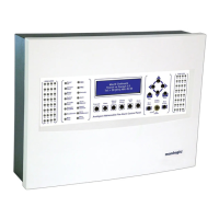
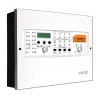
Explains the function of various buttons on the panel for system control and operation.
Describes the purpose and illumination of each LED indicator on the front panel.
Details the SEND and RECEIVE LEDs on the SLCU for communication status.
Lists and describes the self-resetting and glass fuses used within the panel for protection.
Guides through the initial setup and powering of the panel, including cabling and device determination.
Explains the process of rebooting a panel with existing configuration data.
Describes the basic access level with limited button functionality.
Provides access to more menu functions with specific button controls and menu navigation.
Offers special settings and advanced configuration requiring a password.
| Brand | Maxlogic |
|---|---|
| Model | ML-121X |
| Category | Control Panel |
| Language | English |