4-55
Remove the facia (See page 4-50).
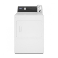
Remove the 7/16” hex nut that secures the
cam on the shaft.
Remove the retainer nut that secures the
bracket to the collar.
Push the lock out the front of the dryer.
Remove the service switch and bracket.
Disconnect two wire connectors.
TECH TIP:
The service switch requires a
key to activate. The key is supplied with
the dryer, and may be in the installation
package or taped inside the front lower
service panel of one of the dryer pockets.
Depending on the age of the dryer the key
may be coded ZB7 or 777.
1.
2.
3.
4.
5.
6.
REMOVE SERVICE
SWITCH ASSEMBLY
7/16” Hex Nut
Electrical Shock Hazard
Disconnect power before servicing.
Replace all parts and panels before
operating.
Failure to do so can result in death or
electrical shock.
Remove the facia (See page 4-50).
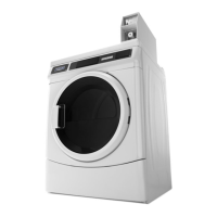
Reach into the opening to the left of the coin
drop and disconnect the 9 pin connector
that supplies power and control to the upper
dryer.
1.
2.
DISCONNECT UPPER
DRYER POWER SUPPLY
Plug
Electrical Shock Hazard
Disconnect power before servicing.
Replace all parts and panels before
operating.
Failure to do so can result in death or
electrical shock.