EasyManua.ls Logo

Maytag MFS25PN - Section 5. Specifications & Wiring Schematics; Fuse Chart; Current Overload Protector Settings

Maytag MFS25PN
65 pages
Print Icon
To Next Page IconTo Next Page
To Previous Page IconTo Previous Page
Loading...
SECTION
5.
SPECIFICATIONS & WIRING SCHEMATICS
All
specifications
used
in
this
section
are
approximate
and
should
be
used
only
as a
general
guide.
These
figures
are
subject
to
change
without
notice.
For
specifics
for
the
product
consult
the
"Installation
Manual"
that
comes
with
the
product
and/or
"Wiring
Diagram."
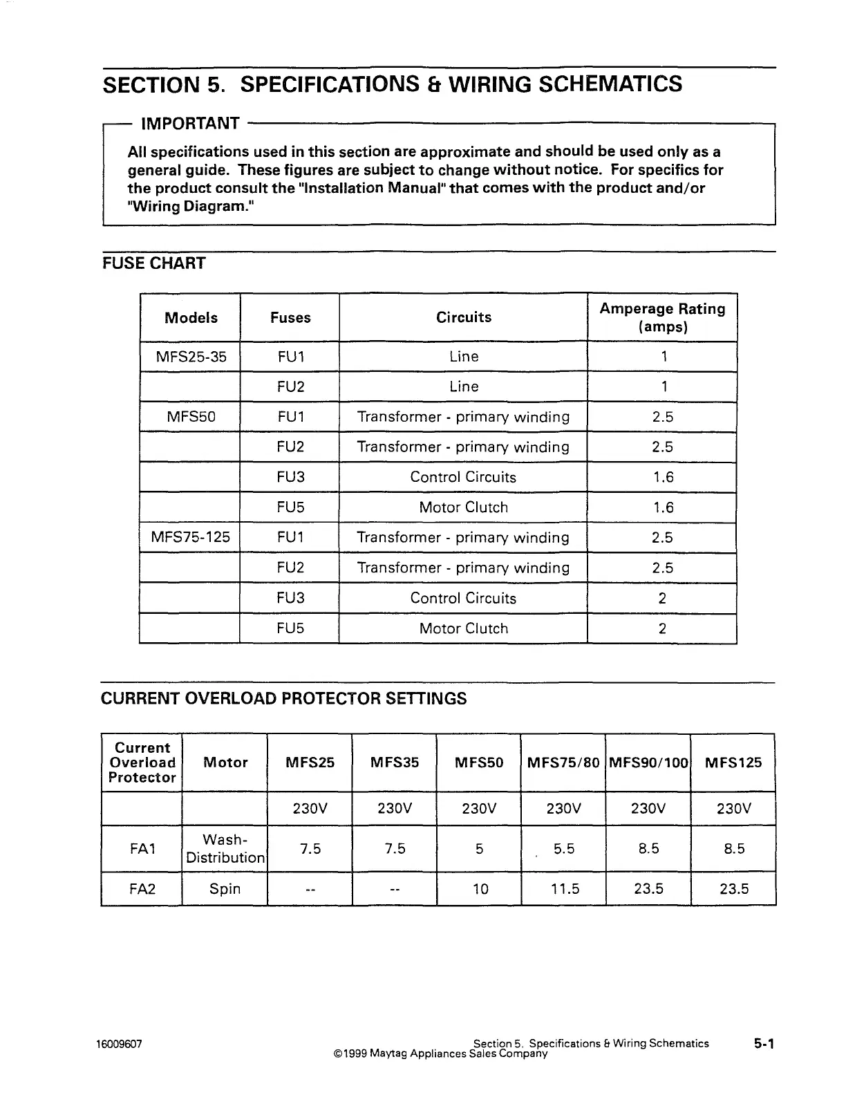
FUSE CHART
Models
Fuses
Circuits
Amperage
Rating
(amps)
MFS25-35
FU1
Line
1
FU2
Line 1
MFS50
FU1
Transformer - primary
winding
2.5
FU2 Transformer - primary
winding
2.5
FU3
Control Circuits
1.6
FU5
Motor
Clutch
1.6
MFS75-125
FU1
Transformer -
primary
winding
2.5
FU2 Transformer - primary
winding
2.5
FU3 Control Circuits
2
FU5
Motor
Clutch
2
CURRENT OVERLOAD PROTECTOR SETTINGS
Current
Overload
Motor
MFS25
MFS35
MFSSO
MFS75/80
MFS90/100 MFS125
Protector
230V
FA1
Wash-
7.5
Distribution
FA2
Spin
--
16009607
230V 230V 230V 230V
7.5
5
5.5
8.5
--
10
11.5 23.5
Section
5.
Specifications & Wiring Schematics
©1999 Maytag
Appliances Sales Company
230V
8.5
23.5
5-1