EasyManua.ls Logo

Maytag MFS25PN - Electrical Requirements; Motor Horsepower (KW)

Maytag MFS25PN
65 pages
Print Icon
To Next Page IconTo Next Page
To Previous Page IconTo Previous Page
Loading...
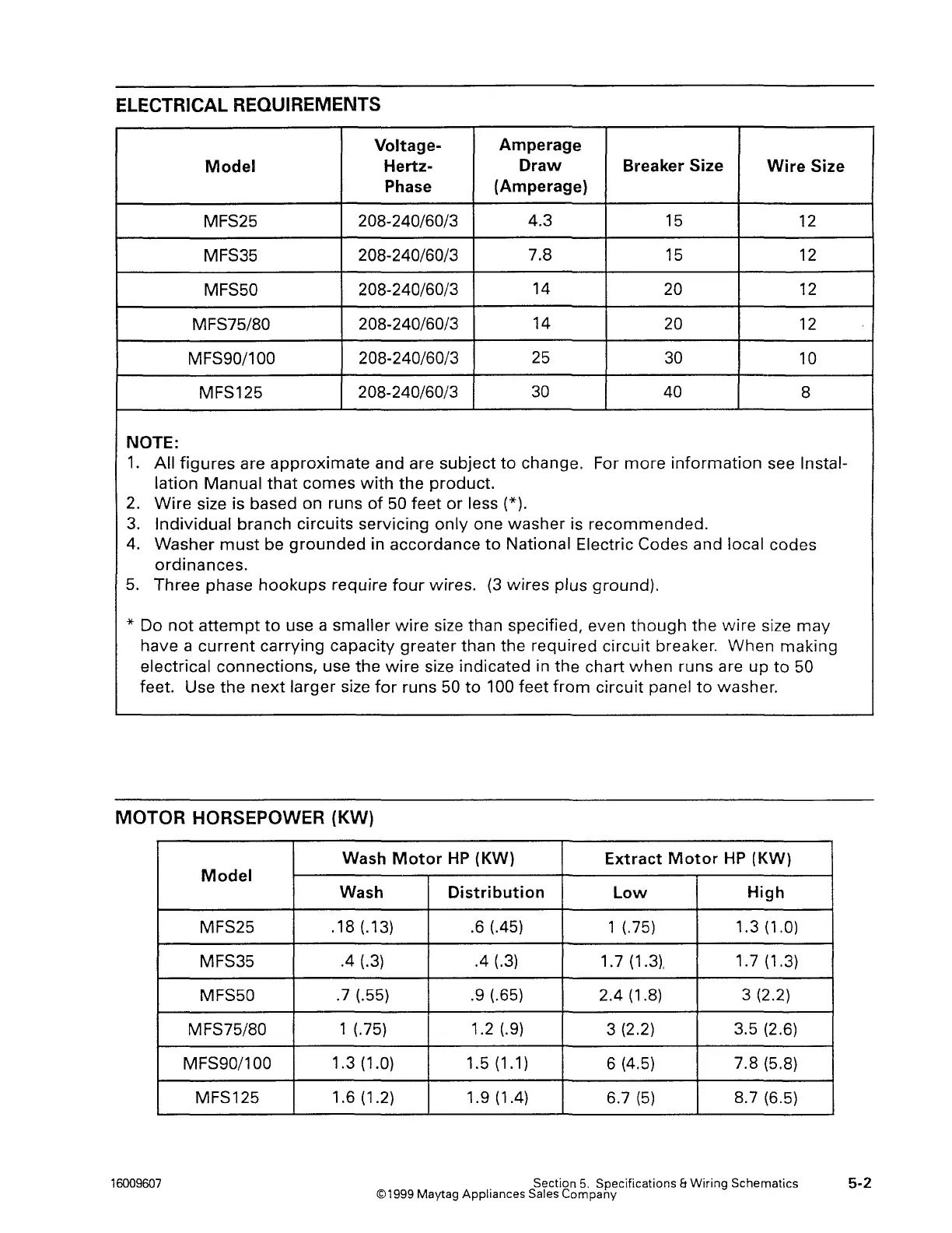
ELECTRICAL REQUIREMENTS
Voltage-
Amperage
Model
Hertz-
Draw
Breaker Size
Wire
Size
Phase
(Amperage)
MFS25 208-240/60/3
4.3
15
12
MFS35
208-240/60/3
7.8
15 12
MFS50
208-240/60/3
14
20
12
MFS75/80
208-240/60/3
14
20
12
MFS90/100
208-240/60/3
25
30
10
MFS125
208-240/60/3
30
40
8
NOTE:
1.
All
figures
are
approximate
and are
subject
to
change. For
more
information
see lnstal-
lation
Manual
that
comes
with
the
product.
2.
Wire
size is based on runs
of
50
feet
or
less (*).
3.
Individual
branch
circuits
servicing
only
one
washer
is
recommended.
4.
Washer
must
be
grounded
in accordance
to
National Electric Codes and local codes
ordinances.
5.
Three
phase
hookups
require
four
wires.
(3
wires
plus
ground).
* Do
not
attempt
to
use a
smaller
wire
size than specified, even
though
the
wire
size
may
have a
current
carrying capacity greater than
the
required
circuit
breaker.
When
making
electrical
connections,
use
the
wire
size indicated in
the
chart
when
runs are
up
to
50
feet. Use
the
next
larger
size
for
runs 50
to
100 feet
from
circuit
panel
to
washer.
MOTOR HORSEPOWER (KW)
Model
MFS25
MFS35
MFS50
MFS75/80
MFS90/100
MFS125
16009607
Wash
Motor
HP
{KW)
Extract
Motor
HP
(KW)
Wash
Distribution
Low
High
.18 (.13) .6 (.45) 1 (.75) 1.3 (1.0)
.4 (.3)
.4
(.3)
1.7
(1.3),
1.7 (1.3)
.7 (.55) .9 (.65) 2.4 (1.8)
3 (2.2)
1 (.75)
1.2 (.9)
3 (2.2) 3.5 (2.6)
1.3
(1.0) 1.5 (1.1)
6 (4.5) 7.8 (5.8)
1.6(1.2)
1.9(1.4)
6.7
(5)
8.7 (6.5)
Section
5.
Specifications &
Wiring
Schematics
©1999 Maytag Appliances
Sales Company
5-2