10
Electrical Connection
Check the data plate to determine electrical requirements.
Before making the electrical connection, make sure the voltage
and frequency listed on the data plate matches your electrical
network. Each washer must be on an individual branch circuit. To
ensure uninterrupted electrical current, a residual current device
(RCD) and a circuit breaker must be installed in the building’s
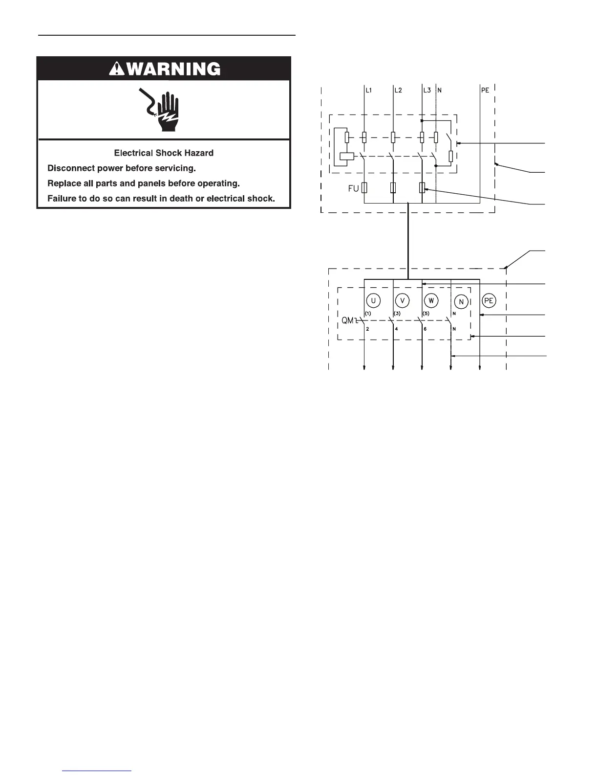
electrical system for each washer. The proper connection is
described in the illustration on the right.
IMPORTANT:
■ If the washer is not equipped with a main switch, supply
disconnecting devices need to be installed in accordance
with EN 60204-1 standard 5.3.
■ Make sure the supply voltage is always within the limits
specied in “Technical Specications.” If the electrical
installation requires long distances to travel, it may be
necessary to use larger cables to reduce the voltage drop.
1. Residual current device (RCD)
2. Laundry electrical main switch
3. Power supply protection
4. Washer
5. Phase conductors
6. Protective conductor
7. Main switch inlet terminal
8. Neutral conductor
Washer Connection to Electrical Network
(with a residual current device)
1
2
3
4
5
6
7
8