Ice ‘N Water Systems
©2005 Maytag Services 16025628 37
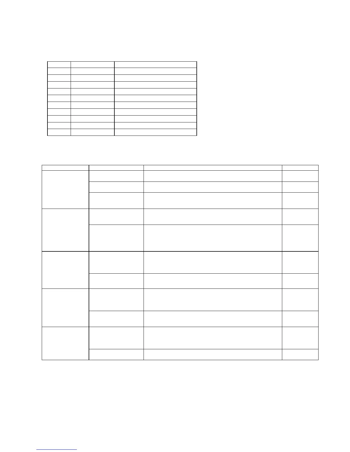
Table A: Harness 10-pin Connector Configuration
Pin Color Signal
1 GY Ice Door Chute Solenoid
2 BR Dispenser Light
3 BU Crushed
4 OR Cubed
5 BK Line Out
6 RD Main Actuator
7 YL Water Valve
8 VT Line In
9
10 WH Neutral
Note: All voltage measurements are referenced to line neutral or pin 10 (WH wire) of 10-pin connector.
Symptom Possible Cause Test Procedure Repair
Switch failure in
freezer door.
With unit powered, open freezer door. Press freezer door
switch in. If freezer light does not turn off, switch is defective.
Replace
switch.
Incorrect harness
wiring.
Verify wire color on 10-pin connector. Refer to Table A. Correct
wiring.
No LED lit
No power to the PCB. With unit powered, measure voltage between (WH wire) and
(VT wire) pin 8 of 10-pin connector. Meter should read
120VAC.
Replace PCB
if meter reads
120VAC.
No continuity.
Disconnect power. Measure continuity between (BR wire) pin
2 of 10-pin connector and dispenser lamp terminal.
Repair open
connection.
No dispenser light
when Main or
Water dispenser
switch is pressed
in Water, Crushed
or Cubed mode.
Failed light bulb or
PCB.
With unit powered, press the Main dispenser switch.
Measure voltage on pin 2 (BR wire) of 10-pin connector.
Voltage should read 120 VAC.
Replace
dispenser
light bulb if
voltage reads
120 VAC.
Failed Main dispenser
switch (failed short)
Disconnect power. Remove both leads from the switch and
measure resistance across switch terminals. Resistance
should read less than 1 Ω in this position and higher than 10
MΩ when switch is open.
Replace
switch
Dispenser light is
on without
pressing the Main
or Water dispenser
switch in Water,
Crushed or Cubed
mode.
Failed PCB
With PCB powered, measure voltage on pin 3 (BU wire) of 10-
pin connector. Voltage should read 0 VAC.
Replace PCB.
Failed Main dispenser
switch (failed open)
Disconnect power. Remove both leads from the switch and
measure resistance across switch terminals. Resistance
should read less than 1 Ω in this position and higher than 10
MΩ when switch is open.
Replace
switch.
Water LED is
illuminated but
does not dispense
water when Main
dispenser switch is
pressed.
No continuity
Disconnect power. Remove the cover of freezer door hinge
located on top of the unit and disconnect the connectors.
Check OR wire (pin 4 of 10-pin connector) for continuity.
Repair open
connection.
Failed Main dispenser
switch (failed short)
Disconnect power. Remove both leads from the switch and
measure resistance across switch terminals. Resistance
should read less than 1 Ω in this position and higher than 10
MΩ when switch is open.
Replace
switch.
Water starts to
dispense as soon
as Water mode is
selected without
pressing the Main
dispenser switch
Failed PCB
With PCB powered, measure voltage on pin 7 (YL wire) of 10-
pin connector. Voltage should read 0 VAC.
Replace PCB.
 Loading...