35
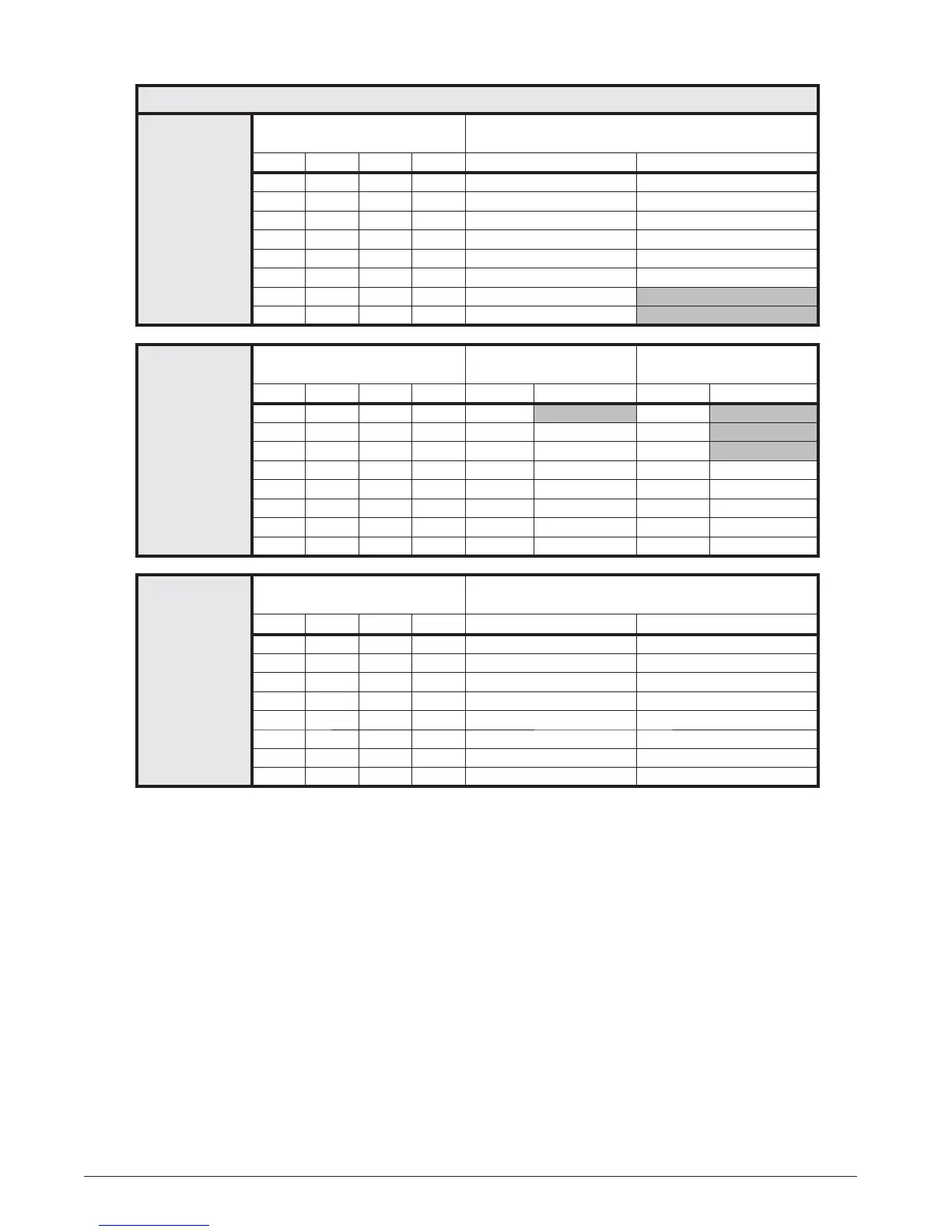
*TC / TL FURNACES WITH VARIABLE SPEED BLOWERS
“B” CABINET
Switch Settings for Heat
(0 = OFF, 1 = ON)
*TC / TL - 060D - VB
Input (BTU) 60,000
1 2 3 4 CFM Temp Rise (° F)
1 0 0 0 1,000 53
1 0 0 1 1,100 48
1 0 1 0 1,200 44
1 0 1 1 1,300 41
1 1 0 0 1,400 38
1 1 0 1 1,500 35
1 1 1 0 1,600 33
1 1 1 1 1,700 31
“C” CABINET
Switch Settings for Heat
(0 = OFF, 1 = ON)
*TC / TL - 080D - VC
Input (BTU) 80,000
*TC / TL - 100D - VC
Input (BTU) 100,000
1 2 3 4 CFM Temp Rise (° F) CFM Temp Rise (° F)
# 0 0 0 1,000 70 1,000 88
# 0 0 1 1,115 63 1,115 79
# 0 1 0 1,230 57 1,230 72
# 0 1 1 1,345 52 1,345 65
# 1 0 0 1,460 48 1,460 60
# 1 0 1 1,575 45 1,575 56
# 1 1 0 1,690 42 1,690 52
# 1 1 1 1,805 39 1,805 49
“D” CABINET
Switch Settings for Heat
(0 = OFF, 1 = ON)
*TC / TL - 120D - VD
Input (BTU) 120,000
1 2 3 4 CFM Temp Rise (° F)
# 0 0 0 1,500 70
# 0 0 1 1,615 65
# 0 1 0 1,730 61
# 0 1 1 1,845 57
# 1 0 0 1,960 54
# 1 0 1 2,075 51
# 1 1 0 2,190 48
# 1 1 1 2,305 46
Notes:
1. Two openings are recommended for airfl ows above 1,600 CFM if the fi lter(s) is (are) adjacent to the furnace.
2. Temperature rises in the table are approximate. Actual temperature rises may vary.
3. Temperature rises shaded in grey are for reference only. These conditions are not recommended.
# Switch not used- can be 0 or 1.
Table 9. Nominal Heating Airfl ows (CFM) & Temperature Rises (°F)