47
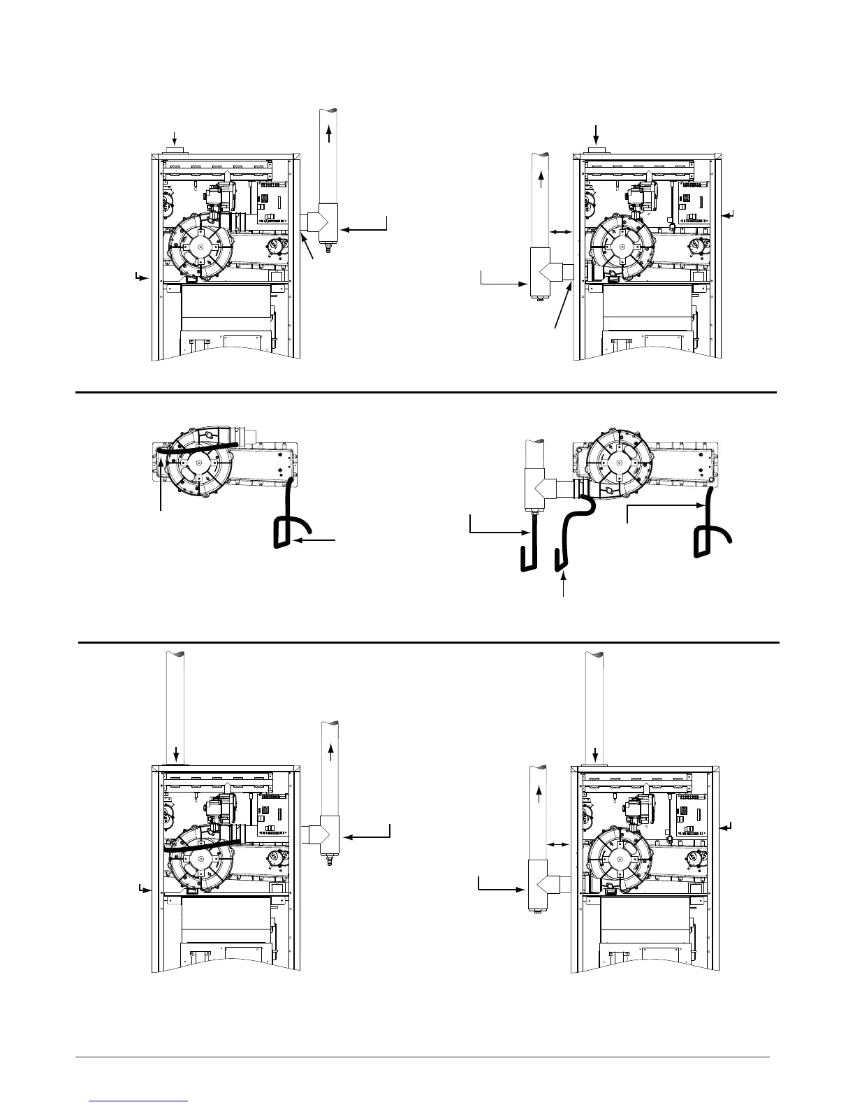
UPFLOW - 1 PIPE OPTIONS
UPFLOW - 2 PIPE OPTIONS
Plug
Plug
Plug
VIEW -B-
Inline
Drain
VIEW -A-
Plug
X
X
OPTION 1
See VIEW A for drain line positions
Rubber
Grommet
PVC TEE,
Reducer, &
1/2” x 1/2”
Hose Barb
PVC TEE,
Reducer, &
1/2” x 1/2”
Hose Barb
OPTION 2
See VIEW B for drain line positions
1.) All drain lines must be trapped with J-Trap or field supplied loop.
2.) Drain line traps may be positioned inside or outside the cabinet.
3.) Inline drain tubing may need to be cut to length to resemble illustration.
NOTES:
Header box drain
tubing is routed thru
the blower deck and
side of cabinet.
Header box drain
tubing is routed thru the blower
deck and side of cabinet.
Drain Line Attached to
1/2” x 1/2” Hose Barb
Rubber
Grommet
OPTION 3
See VIEW A for drain line positions
Inline Drain - Tubing is routed thru the blower deck and side
of cabinet. NOTE: This drain not needed if “X” is less than 6”.
OPTION 4
See VIEW B for drain line positions
PVC TEE,
Reducer, &
1/2” x 1/2”
Hose Barb
PVC TEE,
Reducer, &
1/2” x 1/2”
Hose Barb
COMBUSTION
AIR
COMBUSTION
AIR
FLUE PIPE
FLUE PIPE
FLUE PIPE
FLUE PIPE
COMBUSTION AIR
COMBUSTION AIR
Figure 38. Upfl ow Options