48
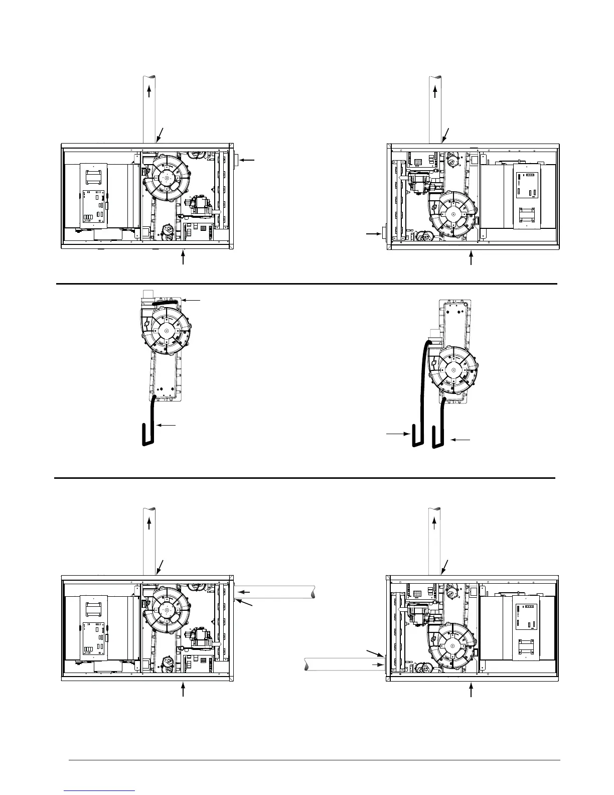
Figure 39. Horizontal Options
Plug
Option
7
Option
8
Inline
Drain
Header Box
Drain
Header Box
Drain
VIEW -C-
VIEW -D-
Inline
Drain
FLUE PIPE
AIR FLOW
1 2 3
4
5 6 7
8
COMBUSTION
AIR
HORIZONTAL RIGHT - 1 PIPE OPTION
FLUE PIPE
COMBUSTION
AIR
Rubber
Grommet
Rubber
Grommet
Plug
FLUE PIPE
Rubber
Grommet
COMBUSTION AIR
FLUE PIPE
AIR FLOW
1 2 3
4
5 6 7
8
Rubber
Grommet
COMBUSTION AIR
See VIEW C for
drain line positions
See VIEW C for
drain line positions
See VIEW D for
drain line positions
Plug
Plug
See VIEW D for
drain line positions
1.) All drain lines must be trapped with J-Trap or field supplied loop.
2.) Inline drain tubing may need to be cut to length to resemble illustration.
NOTES:
Flange
Flange
Option
5
Option
6
HORIZONTAL LEFT - 1 PIPE OPTION
HORIZONTAL LEFT - 2 PIPE OPTION
HORIZONTAL RIGHT - 2 PIPE OPTION