01-2021 MC-Bauchemie Müller GmbH & Co. KG 11
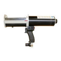
4) PRODUCT OVERVIEW
Refer to the figures {A} to {I} on page 2:
1 Cartridge guide
2 Plunger discs*
3 Dispense volume indicator
4 Pneumatic drive unit
5 Cartridge ejector button
6 Cartridge holder*
7 Trigger
8 Pressure regulation valve
9 Handle
10 Retract Button
11 Retaining Nut
12 Nose Plug
13 Instruction handbook
14 Compressed air connection
* available as a spare part
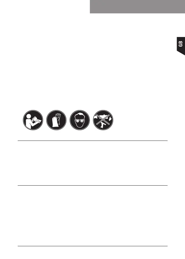
Safety instructions stickers
5) FUNCTIONAL DESCRIPTION
Refer to the figures {A} to {I} on page 2:
The air pressure in the pneumatic circuit is lowered by the pressure regulation valve (8).
Air Pressure drives a cylinder piston which moves the mounted plungers (2) into the
cartridge tubes and forces material into the static mixer.
6) PREPARING THE DISPENSER FOR USE
Procedure
Refer to the figure {A} on page 2:
1. Install desired ¼” NPTF or BSPPF quick-release coupling (not included) using
two wrenches to tighten.
2. Connect dispenser to compressed air line and verify connection for air leaks.
May need to tighten connection if leaks are discovered.
Instruction handbook