8
Insert a 4 mm round pn and lock the
ackerman plate to prevent steerng(3,2).
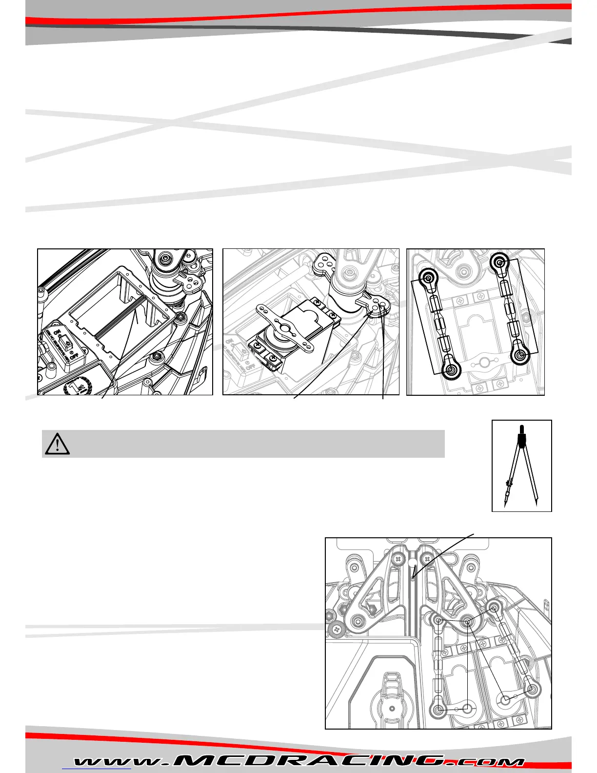
Figure L
C A
D
D
E
E
A
B
Servo 1
Servo 2
1. Cut the beam wth a dagonal plers as ndcated n Figure H.
2. Install servo as shown n Figure I.
3. Insert a 4 mm round pn and lock the Ackerman plate to prevent steerng as shown n Figure L. Servo saver wll be locked
n the central poston.
4. Turn on the rado and nstall the double horn to neutral poston. Perpendcular to servo case.
5. Set steerng EPA to approx. %70.
6. Set from the sub trm menu the dstances from “the servo horn” to “servo saver” equal at both sdes as shown n Figure J.
You can use a dvder to measure the dstance. (Figure K)
7. Assemble the lnkages suppled n the accessory bag and adjust them to same lengths measured n step 6.
8. Install the assembled lnkages to the outer holes on the servo saver as ndcated n Figure I and Figure J.
9. Remove the round pn nserted n step 3.
10. Adjust steerng EPA to max. possble left then max. possble rght from the transmtter. The servo should stop turnng
when the steerng reaches ts maxmum travel.
11. After step 10 s completed your steerng sngle servo nstallaton and set-up s fnshed.
1. Install servos as shown n Figure L.
2. Insert a 4 mm round pn and lock the Ackerman plate to prevent steerng as shown n Figure L.
Servo saver wll be locked n the central poston.
3. Turn on the rado and nstall the sngle horns to neutral poston as shown n Figure L.
4. Set steerng EPA to approx. %70.
5. Measure the distance A shown n Figure L wth a dvder.
6. Set from the sub trm menu, the servo 1 horn dstance to servo saver
nner hole(distance B) s equal to distance A.
7. Repeat step 6 for servo 2 distance C and check f the distance B has
remaned same.
Dstances may change durng sub trm. Remove the horns of servo 1
and servo 2 and swap them then repeat step 5,6 and 7.
Make sure the distances A, B and C are equal!
8. Assemble the lnkages suppled n the accessory bag wth the same
length wth distance A.
9. Install the assembled lnkages to the nner hole on the servo saver for
faster response (make sure the distance D s equal to the servo horn
distance E as shown n Figure L).
10. Remove the round pn nserted n step 2.
11. Adjust steerng EPA to max. possble left then max. possble rght from
the transmtter. Be sure the servo stops turnng before the steerng
reaches ts maxmum travel.
12. After step 11 s completed your steerng sngle servo nstallaton
and set-up s fnshed.
You can use sngle or double steerng servos on ths car. We recommend usng large scale 30x60mm mn of 25kg/cm
torque servos.
Double-servo nstallaton s crtcal and should be handled carefully. If not nstalled
properly the servos wll work aganst each other and damage themselves.
Figure I
Steering single-servo installation.
Steering double-servo installation.
Steering servo installation.
Figure J
Sngle servo hole Twn servo holes
Figure H
Cut the beam wth dagonal plers(1).
Figure K
x
x
Caution!