not affected by the position of the loudness control.
EQUALIZER AMPLIFIER
The equalizer amplifier is constructed with another
of the same type low noise operational amplifier as
used in the phono amplifier. Three other operational
amplifiers are arranaged in circuit configurations that
are the equivalent of three series tuned circuits. One
is resonant at each of the three equalizer center fre-
quencies. These series tuned circuits are inserted via
the control potentiometers in either the input circuit
or feedback circuit of the equalizer amplifier thereby
providing a boost and cut capability of 12 dB for each
band of frequencies. The equalizer amplifier has a flat
response gain of 0 dB.
OUTPUT/HEADPHONE AMPLIFIER
The output amplifier is a push-pull complementary
class AB amplifier using a signal inverting differential
stage at its input. This amplifier drives the main out-
puts and the headphone jack. More than 10 volts RMS
output can be produced with typically no more than
0.003% harmonic distortion.
A turn-on delay circuit is located ahead of the out-
put amplifier. This circuit uses a light emitting
diode/light dependent resistor network that functions
to transmit no signal until two seconds after the
power switch is turned on and to remove the output
signal almost instantly upon power turn-off. Thus the
turn-on and turn-off is transient and noise free.
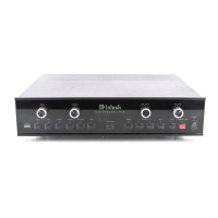
INPUT SELECTOR SWITCHING
Low level, noise critical input selector switching is
done electronically using field effect transistor
analog switches. The front panel selector simply swit-
ches small amounts of control DC which turn the FET
analog switches off or on. This design eliminates
degradation of frequency response and noise pickup
from long signal paths necessary with conventional
switching.
POWER SUPPLY
To minimize magnetic hum radiation and thus im-
prove signal to noise ratio the C 504 power
transformer is triple shielded. Shielding includes a
copper strap, a silicon steel strap, and finally a steel
outer shell. The transformer output voltage is fed to a
full wave bridge rectifier and 3,300 microfarad filter
capacitors to provide the +24 volts for powering the
plus regulator and -24 volts for the minus regulator.
Integrated circuit voltage regulators supply the ±18
volts needed for low level amplifier stages.
-11-
 Loading...