17
16. Connect Cables from the Turntable (with a Moving Coil
Cartridge) to the C1000 Tube Preamplifier Unbalanced
MC (9) LEFT and RIGHT INPUTS.
Note: If the Turntable has a Moving Magnet Cartridge,
connect the cables to the MM (8) Inputs.
17. Connect the Turntable Ground Cable to the GND bind-
ing post located between the C1000 Tube Preamplifier
MC (9) LEFT and RIGHT INPUTS.
18. Connect Cables from the External Sound Processor Left
and Right Inputs to the C1000 Tube Preamplifier PRO-
CESSOR TO LEFT and RIGHT Output Jacks.
19. Connect Cables from the External Sound Processor Left
and Right Outputs to the C1000 Tube Preamplifier
PROCESSOR FROM LEFT and RIGHT Input Jacks.
20. Connect Cables from the Music Server Left and Right
Outputs to the C1000 Preamplifier Unbalanced SRVR
(4) LEFT and RIGHT INPUTS Jacks.
21. Connect Cables from the Music Server Left and Right
Inputs to the C1000 Preamplifier Unbalanced SRVR (4)
LEFT and RIGHT OUTPUTS Jacks.
22. Connect an XLR Cable from the C1000P RECORD
LINK LEFT INPUT to the C1000T RECORD LINK
LEFT INPUT Balanced Connectors.
Note: The Record Link Connections allow sharing of the
Inputs between the C1000P and C1000T for
recording purposes.
23. Connect an XLR Cable from the C1000P RECORD
LINK RIGHT INPUT to the C1000T RECORD LINK
RIGHT INPUT Balanced Connectors.
24. Connect XLR Cables from the C1000 Preamplifier
MAIN LEFT and RIGHT Balanced OUTPUTS, to one
of the Balanced Inputs on the Left and Right McIntosh
Power Amplifiers.
25. Connect XLR Cables from the C1000 Tube Preampli-
fier MAIN LEFT and RIGHT Balanced OUTPUTS, to
the remaing Balanced Inputs on the Left and Right
McIntosh Power Amplifiers.
Notes: 1. If the Power Amplifiers used do not have a
pair of Balanced Inputs connected in parallel,
then use the supplied Balanced Line Integrator
between the C1000 and the Power Amplifiers.
Refer to figure 1 on page 18.
2. The Unbalanced SPKR1/SPKR2 from the
C1000P may not be combined with SPKR1/
SPKR2 from the C1000T.
3. If the C1000 is part of a Multichannel Audio
System, proceed to page 19 at this time.
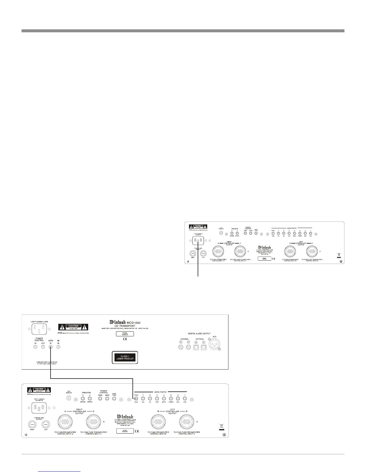
26. Connect the supplied AC Power Cord between C1000C
AC Power Cord Socket and a live AC outlet. Refer to
figure B.
27. Proceed to page 23 for customizing the SETUP Fea-
tures for the C1000 Preamplifier and C1000 Tube
Preamplifier.
Connect
Figure B
Figure A
 Loading...