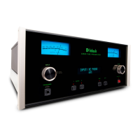
Output Connections.
Two
sets of
outputs
have
been
provided .
One
s
et
is
the
"
MAIN
OUTPUT"
to
feed
the
power
arnpli-
f ie r
s
and the othe
r is
the
'
'
TAPE
OUTPUT"
to
feed
a
tape recorder.
The
'rTAPE
OUTPUT"
is
unaf
-
fe
cted by
any adj
us trne
nts
rnade with
the
f ollowing
controls
:
"
MODE
SE
-
LECTOR,
"
"BALANCE,'|T
'|rPHASE",
"LOUDNESS,'r
'|BASS, " "TREBLE, " "RUMBLE
FILTER,
"
and
"VOLUME.
"
Any adjustrnents
made in the
'TINPUT
SELECTOR,
" "RECORD
COMPENSATOR,
"
and the
"HF
CUTOFF
FIL-
'TER"
do
effect
the
signal at
the
"TAPE
OUTPUT"
jacks
if the signal originates in the
phonoor
tape
head
inputs.
The
rnain and
tape
output
jacks
are fed from cathode
followers.
The input
irnpedance of
devices
connected to these outputs
should be
50,000
ohrns or
greater,
and the capacitive react-
ance of audio cables connecting
these devices should not be less than
8,000 ohrns at 20,000
cycles. This
is the reactance of
a
capacity of
1,000 rnrnf.
Audio
cable
having a
capacity of
25 mmf
per
foot
rnay be 40 feet long,
13.5
mmf
per
foot cable may
be
75
feet long.
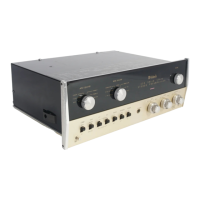
C-20
Prearnplifiers Serial
No.
6
L7
0
0 and
late r harre an
additional
left
plus right output
jack.
A
rnono-
phonic
s
ignal can
be distributed
to
other
roorns by.onnecting
this
jack
to
a
powe r
arnplifie
r
to
drive the
ffronophonic
louds
peakers .
The
ca-
ble c
onne cting
to this
o utput
should
not
have a capacity
of rrrore than
3
00 rnrnf .
The
input
irnpedance
of
the
powe r arnplif ie
r
c
onne cting
to
this
output
should
not
be le s s than
I50,000
ohrns
(150
K).
Thegenera-
tor
irnpedance
at
this
output
is
ap-
proxirnately
7,3, 000
ohrns
(23
K).
Connecting
Prograrn Source
Grounds.
A
single ground
post is
provid-
ed.
The chassis
ground frorn turn-
table,
r€cord
change
rs
(rnotors
used
with each),
tape
<iecks,
etc.,
should be
returned to this
post.
Do
not duplicate
this
ground circuit.
Unde
s irable
hurn will be
he ard in
the
systenr
alrnost certainly
if
duplicate
ground
returns are used.
The left
and right
prograrn
cables
frorn each
source should
be twisted.together
and the
ground
wire
frorn
each source
can
be
wound
or twisted
in
with these cables.
To
avoid hum,
rnake sure that
the
ground
wire does
not
make
any connections
to
shields
of the
left and
right channel
cables
except for the connec-
tion
provided
with the C-20
ground
post
I
@
I
@
..r;*@o'
,ro.'@);^
Rlen*@
o!o
o\.
-ll-