MOUNTING INSTRUCTIONS
(Serial
No.
6L001
and
Later)
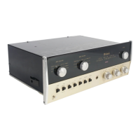
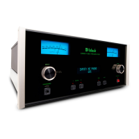
Your
C-20
Stereo Prearnplifier
rnay
be
rnounted in
a cabinet
of
your
own, in
the Mclntosh
Cabinet Model L-66,
ot on a
rack panel.
MOUNTING IN YOUR OWN CABINET.
This
prearnplifier
has been designed to mount on
a shelf or from the front
panel
if
the
panel
thickness
is
3/8"
or rnore. It is
suggested that the instructions be
read
through
com-
pletely
before
starting
the installation.
Enclosed
in the Instruction
Manual envelope
are two copies of the
"WOODEN
PANEL
CUTOUT TEMPLATE"
and
two copies
of the
"SHELF
CUTOUT
TEMPLATE'|
for
mounting
the C-20.
Prepare
the cabinet
for the mounting by
first
cutting
the wooden
panel to receive the
pre-
arnplif ie r .
l.
On
the back of the
wooden cabinet
panel
make
a vertical center line on the
exact
center
of the
area in which
the
preamplifier
will rnount.
In the
parts
bag that
was packed with the
prearnplifier there are two metal
mounting
striPs
l/2" wide and 3 I12" Long. The
"WOODEN
PANEL CUTOUT
TEMPLATE"
shows how the
rnounting
strip is
used
as a measuring
guide
to locate the
two
"LOCATION
HOLES.
''
Z. Take the
rnounting strip and with
a
pencil
mark one length
13
LlT"l both to the
right
and to the
left of
the
vertical center
line, approxirnately
one rnounting strip length above
the
sheIf.
Rest the
end of the
rnornting strip on
the shelf and mark
one length
(3
l'2"1
vertically.
Where these
rnarks intersect
is
the
position of
the
"LOCATION
HOLES.
"
3. Drill these
two holes
with a 3/16" drill being careful
to hold the
drill as nearly
per-
pendicular
as possible so as
not
to
transfer any error
in location of the
holes to the front of
the cabinet.
4.
Transfer the
"WOODEN
PANEL
CUTOUT
TEMPLATE"
to the
front of
the wooden
cabinet
panel.
Match the
"LOCATION
HOLES'|
for the
ploper positioning
of
the template.
Caref
ully
drill the
s ix 3
I
I6" rnounting
hole s .
5. Cutout
the
openingin
the
cabinet
keep-
irg within
the
line
s .
If
the
s
aw doe s
not
quite
reach the
line
s, finish the
opening
with a file
or
coarse
sandpaper.
6
.
Us
ing
two
f
lathe
ad
rnachine s
c
re ws
fasten the
two mounting
strips on
the back
of
the cabinet
panel so that the
edge
of the mount-
irg
strip
is
flush
with the edge
of
the cabinet
hole,
and that
the
rnounting
hole s coincide
with
the
mounting
s
trip
nuts
. Two
lengths of
s
c
rews
are
provided f or
diffe
rent cabinet
pan-
eI
thicknesse.
(Flathead
6-32
x
LlZ"
and
6-32
x
I Ll4"l.
IMPORTANT:
The
heads
of the two
flat-
he
ad
rnachine
s c
re
ws holding
the
rnounting
strips
in
place rnust
be
flush
with the
front
s urface
of the cabinet.
If
the
s
crews
will not
p
ull into
the
wood
,
a s light c
ounte
r s ink
with an
oversize
drill
rnay be
necessary.
,@
#
6-32
FLATHEAD
MACHINE
SCREW
/#'
d
Ik
UNTING
STRI P
SPRING
CLI
PS
CABINET PANEL
CUTOUT
-5-
MOUNTING
HOLES