1B
McIntosh Laboratory, Inc. 2 Chambers Street Binghamton, New York 13903-2699 Phone: 607-723-3512 FAX: 607-724-0549
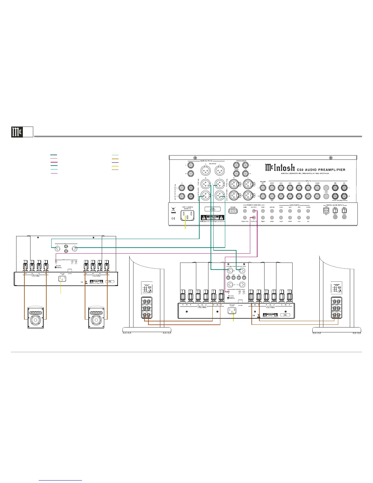
C50 Audio Preamplifier Output and Control Connection Diagram
Note: Refer to the C50 Owner’s Manual page 9 for additional connection information.
Connection Legend:
Data Cable*- Digital Signal Cable -
Sensor/Keypad Cable - RS232 Cable -
Power Control Cable* - Ground Wire -
Audio Signal Cable - AC Power Cords -
Video Signal Cable - Loudspeaker Cable -
RF Signal Cable -
* 2 conductor shielded with 1/8 inch stereo mini phone plug on each end.
+
Connect to
AC Outlet
Power Amplifier - Secondary Room
Connect to
AC Outlet
Connect to
AC Outlet
Right Loudspeaker System Left Loudspeaker System
Right
Loudspeaker
System
Left
Loudspeaker
System
-
+
-
+
-
+
-
Power Amplifier - Primary Room
 Loading...