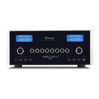
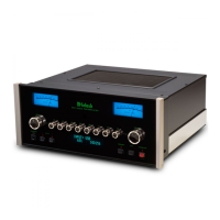
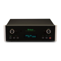
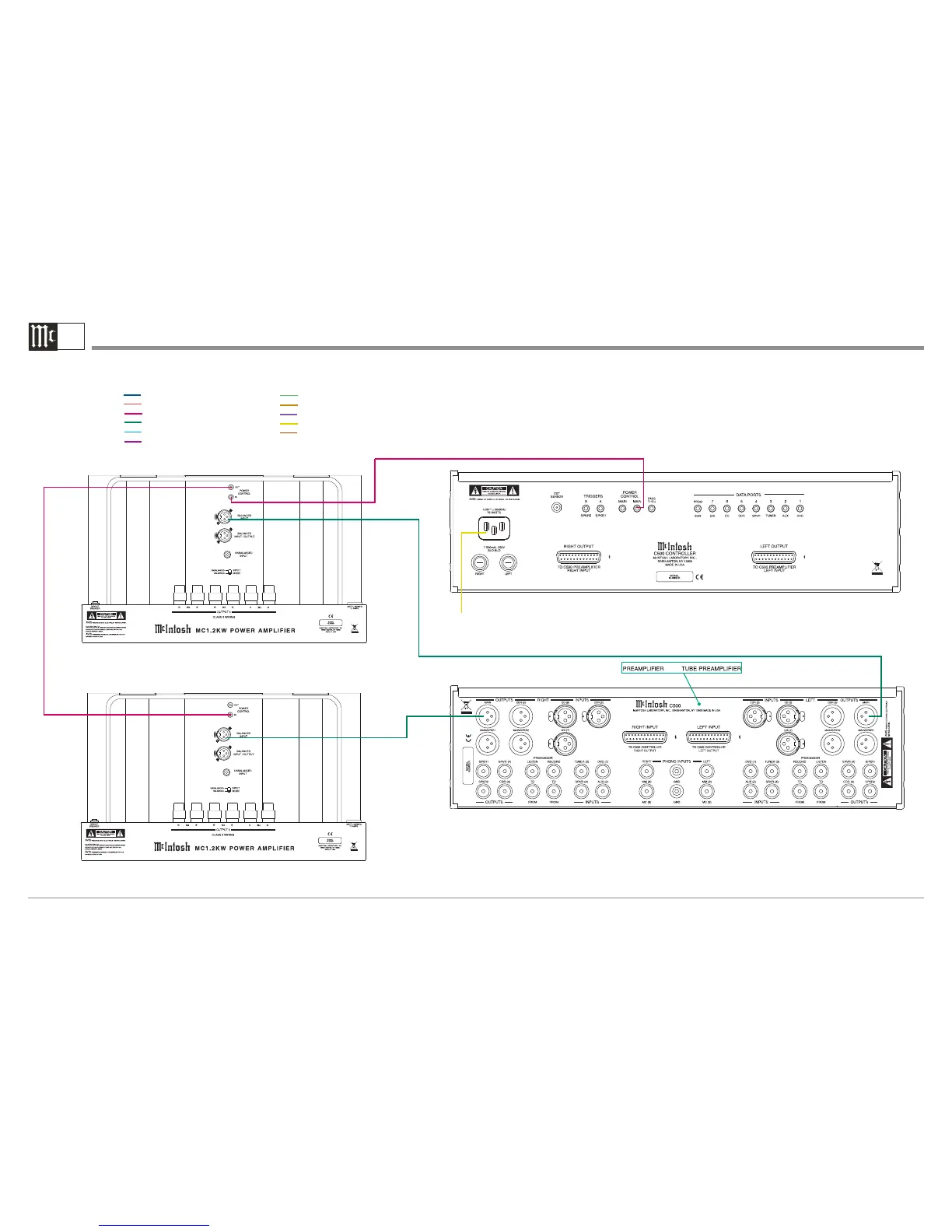
C500 Controller / C500P or C500T Preamplifier Output and Control Connection Diagram
3B
McIntosh Left Channel Power Amplifier
Connect to
AC Outlet
McIntosh Right Channel Power Amplifier
Note: Refer to the C500 Owner’s Manual page 12 for additional connection information.
Connection Legend:
Data Cable*- Digital Signal Cable -
Sensor/Keypad Cable - RS232 Cable -
Power Control Cable* - Ground Wire -
Audio Signal Cable - AC Power Cords -
Video Signal Cable - Loudspeaker Cable -
RF Signal Cable -
*
2 conductor shielded with 1/8 inch stereo mini phone plug on each end.
or
 Loading...