EasyManua.ls Logo

McIntosh C42 Service Manual

McIntosh C42
36 pages
To Next Page IconTo Next Page
Page #1 background imageLoading...
Page #1 background image
AUDIO CONTROL
CENTER
BALANCE
@
FECORO
@@@@@@@@@
LISIEN
2
VOLUME
llltlnlogh
C42
AUDIO
CONTROL CENTER
L R
LINE 1
-
LINÈ2-O
@
35 70 150
300
600
1.2k 4k
o
?g5
CONIENIS
Performance
Specifications ..........
Notes .........
Rear
Panel
Section
Locations
Block Diagram
...................
lnterconnection
Diagram ...
Main Schematic
and PCB...
Balanced
Schematic
Display
Schematic and PCB
Tone
Schematic and
PCB
...
Data Schematic and PCB ...
Parts List.....
Exploded View
and
Parts List...
Repacking lnstructions
...6-1
2
2
3
3
4
5
7
.... 1B-20
....21-24
....25-26
....27-28
....29-31
....32-34
......... 35
mlnt
û5
h
SERVICE MANUAL

Other manuals for McIntosh C42

Question and Answer IconNeed help?

Do you have a question about the McIntosh C42 and is the answer not in the manual?

McIntosh C42 Specifications

General IconGeneral
BrandMcIntosh
ModelC42
CategoryAmplifier
LanguageEnglish

Summary

Unit Specifications and Operating Notes

Performance Characteristics

Electrical and physical performance parameters of the audio control center.

Operational Guidance and Warnings

Notes on schematic interpretation, measurement conditions, and component safety.

Physical Layout and Components

Rear Panel Connectivity

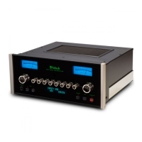
Identification of input, output, and control connectors on the rear panel.

Internal Circuit Board Locations

Diagram showing the placement of major PCBs within the unit.

System Block Diagram

Functional Block Overview

High-level schematic illustrating main functional blocks and signal flow.

Interconnection Diagram

Cable Routing and Connections

Diagram showing how different PCBs are interconnected via cables.

Main PCB Schematic and Layout

Main PCB Component Layout

Diagram showing the physical placement of components on the Main PCB.

Display Section Schematics and PCB

Display PCB Component Layout

Diagram showing component placement on the Display PCB.

Tone Control Schematics and PCB

Tone PCB Component Layout

Diagram showing component placement on the Tone PCB.

Data Section Schematics and PCB

Data PCB Component Layout

Diagram showing component placement on the Data PCB.

Parts List

Component Identification and Part Numbers

Comprehensive list of parts with their numbers and descriptions.

Exploded View of Unit Assembly

Component Assembly Diagram

Illustrated breakdown of the unit's components and their assembly.

Repacking Instructions

Shipping and Packaging Guide

Step-by-step instructions for safely packing the unit for shipment.

Related product manuals