Adequate ventilation extends the trouble-free life
of electronic instruments. It is generally found that
each 10° centigrade (18° F) rise in temperature
reduces the life of electrical insulation by one half.
Adequate ventilation is an inexpensive and effective
means of preventing insulation breakdown that re-
sults from unnecessarily high operating tempera-
tures. The direct benefit of adequate ventilation is
longer, trouble-free life.
Allow at least 15 inches deep x 17½ inches wide
x 6 inches high for mounting the MA 5100. Always
allow for air flow by either ventilation holes or space
next to the bottom of the equipment and a means
for a warm air to escape at the top.
It is recommended that it be mounted in a normal
or horizontal position. However, with adequate venti-
lation the instrument can be mounted in any position.
To prepare the MA 5100 for installation remove the
plastic protective covering. Turn the MA 5100 upside
down so that it rests on its top on the shipping pallet.
Remove the four plastic feet fastened to the bottom
of the chassis.
The professional mounting design eliminates the
need for any shelf or bracket to support the MA 5100.
It is completely supported by its own mounting
brackets.
Position the plastic mounting template over the
area of the cabinet to be cut out for installation.
The design of the mounting template allows the
cutout to be positioned or located from the front
or rear of the panel to which the instrument is to be
mounted.
If the cutout is to be located from the rear of the
panel, the following steps will help you.
On the back of the cabinet panel, scribe a vertical
centerline through the exact center of the area in
which the cutout is to be made.
Place the template against the back of the panel
and match the template centerline with the center-
line on the cabinet panel.
Make sure that there is at least ¼ inch clearance
between the bottom of the dashed line of the cutout
area on the template and any shelf or brace below
the proposed cutout.
Mark the two locating holes ("C" holes on the
mounting template).
Drill the two locating holes. Be certain the drill is
perpendicular to the panel.
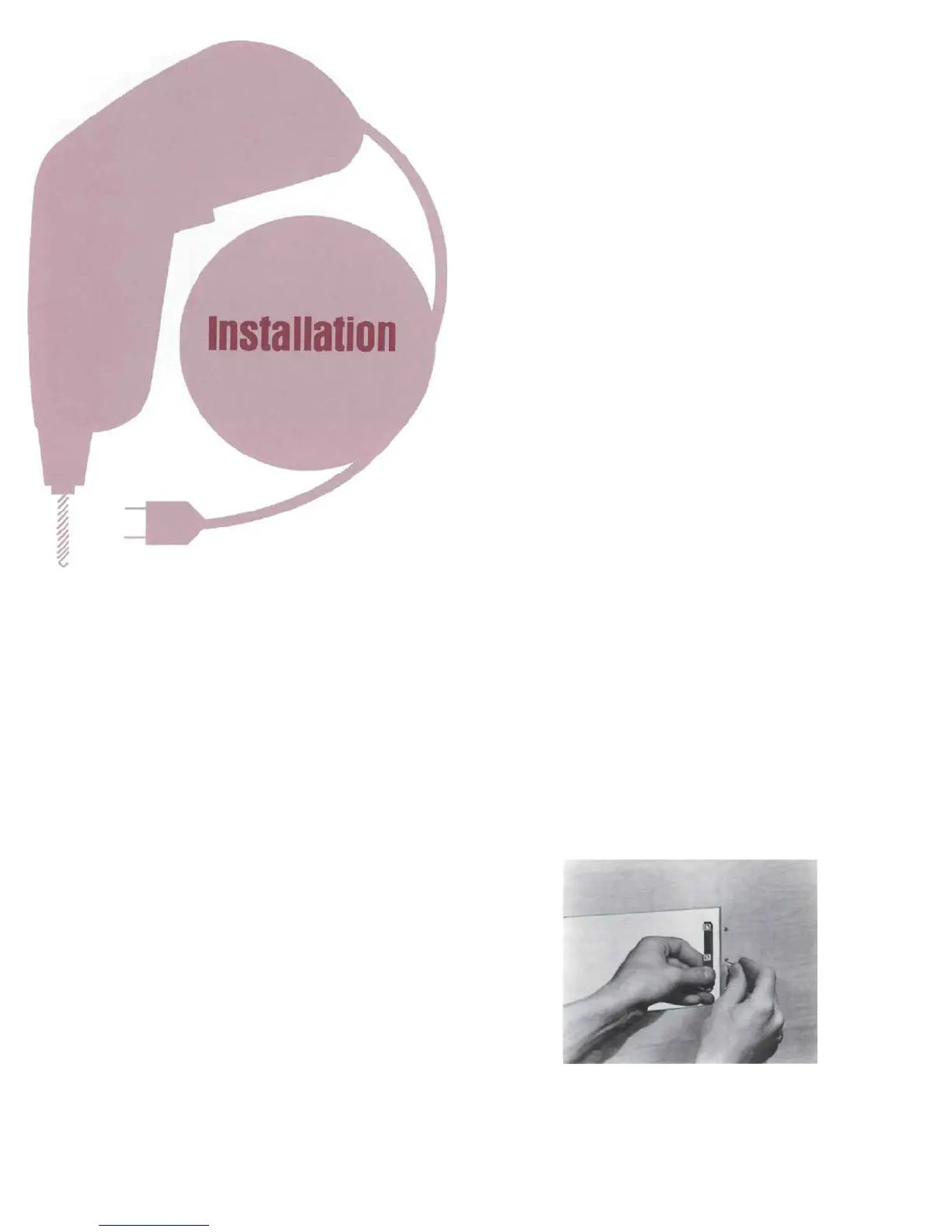
Now position the template on the front of the panel
by aligning the "C" locating holes on the template
with the drill holes.
With template in place against the cabinet panel,
mark the "A" and "B" drill holes and the four small
holes that identify corners of the cutout. Join the
corner marks with a pencil. The edge of the template
can be used as a straight edge.
IMPORTANT: DRILL THE 6 HOLES BEFORE MAK-
ING THE CUTOUT.
Accurately drill the three holes on each side of
the cutout area with a 3/16 inch drill.
With the saw on the INSIDE OF THE PENCIL
LINES carefully cut out the rectangular opening.
2
 Loading...