SCHEMATIC NOTES
1. Unless otherwise specified: Resistance values are in ohms, 1/2 watt, and 10% tolerance;
capacitance values smaller than 1 are in microfarads (µf) ; capacitance values greater
than 1 are in picofarads (pF); inductors are in microhenries (µH).
2.
Printed
circuit
board
components
are
outlined
on the
schematics
by
dotted
lines.
The
circled
numbers
on the
dotted
lines
correspond
to the
numbers
on the PC
board
layouts.
I 3. The heavy lines on the schematics denote the primary signal path.
4. The terminal numbering of rotary switches is for reference only.
5. All voltages indicated on the schematics are measured under the following conditions:
a. Use of an 11 megohm impedance VTVM.
b. All voltages ±10% with respect to chassis ground.
c. Ho signal at input terminals.
d. AC input at 117 volts AC, 50/60Hz.
e. Front panel controls at:
Left Gain
Meter Range
Right Gain
Speakers
Power
FULLY CCW
OFF
FULLY CCW
ON
OH
6. R125, R126, R127, and R128 are 2.7K in early units.
7. R215 and R216 are 1.2K and R217 and R218 are 22K in early units.
8. In
units
with
serial
No's below
10M40:
C111, C112, C113,
and
C114,
are
used; C107, C108,
C109. and C110 (part No. 064-044) are .047; The emitter of Q113 and Q114 is connected as
shown
by the
dotted
line;
R139
and
Rl40 {part
Ho.
139-061)
are
used.
9. In
units with
serial
No's below 11M93: Rl59
and
R160
are not
used; R143, R144, R145, R146,
R147, R148, R149, and R150 are .15W (part Ho. 139-055); pins Ho. 12 and 9 on PC boards
are
connected
as
shown
by
dotted
line.
10.
C125
and
C126
are
used
in
units
with
serial
No's
from
11M93
to
13M05.
11. R137f R138, R141, and Rl42 are 75ohm 9W 10% (part No. 139-070) and R119 and R120 are 2751
in early units.
12. In
units
with
serial
No's below
20M01;
R107, R108, C105,
and
C106
are
used;
ferrite
beads
(part No. 076-010) are not used.
13. In
units
with
serial
No's
below
20M50
R161
and
R162
are not
used
and pin l4 is
connected
as
shown
by
dotted
line.
14.
R155
and
R156
are
8.2ohm
10% in
units
with
serial
No's
from
l0M40
to
21M13.
15.
R109,
110 is 47K in
units
with
serial
No's
from
11M93
to
23M25.
16. In
units
with
serial
No' a
below
10M40;
C117
and
Cll8
are
.0012.
In
units
with
aerial
No's from 10M40 to 23M25, C117 and Cll8 are not used.
17. In
units
with
serial
No's below
23M25,
C115
and
C116
are
.0012.
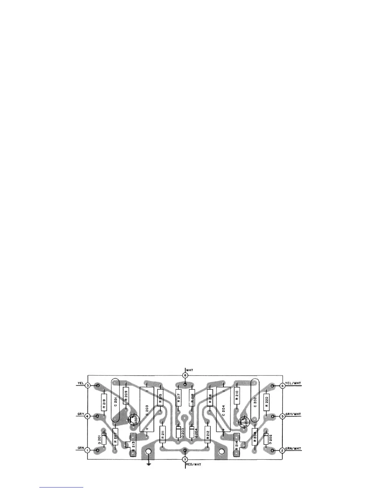
18. Adjust meter calibration controls R213 (left channel) and R214 (right channel) so
output meters indicate +3dB when meter range switch is in the "0" position and the
amplifier is delivering 105 watts output.
METER SECTION PRINTED CIRCUIT BOARD 043-711
 Loading...