4
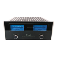
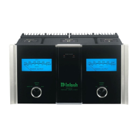
Unpacking the MC1502
Caution: To prevent damage to the MC1502
Vacuum Tubes during shipping,
there is a special foam insert
surrounding the Vacuum Tubes of
the Power Amplifier.
The Foam Insert must be
removed from the MC1502
before connecting the AC
Power Supply Cord to the
Power Amplifier.
Failure to do so has the
potential of a Fire Hazard,
resulting in damage to the
MC1502 and the surrounding
environment.
Follow these instructions for
removal of the packing foam
before connecting the AC
Power Supply Cord to the
MC1502.
In order to remove the foam insert sur-
rounding the Vacuum Tubes on the MC1502, it
is necessary to temporarily remove the opera-
tional Tube Shield Metal Cover. After the foam
insert is removed, the Tube Shield Metal Cover
is to be re-installed for proper and safe opera-
tion of the MC1502 Power Amplifier. The Tube
Shield Metal Cover provides protection from
the hazardous voltages inside the MC1502. The
MC1502 has no user serviceable parts, includ-
ing the Vacuum Tubes. If repairs are needed
they must be performed by an authorized Mc-
Intosh Service Agency.
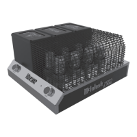
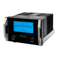
1. Orient the MC1502 so the Front Side of the Power
Amplifier is facing you and remove the Warning
Sheet. Refer to figure 1A.
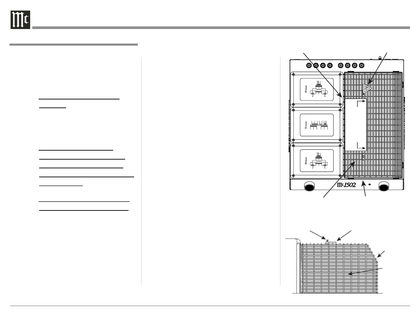
2. Referring to figure 2B (a partial side view of the
MC1502) to temporarily remove the two screws
and the Hot Surface Tag located on the top of the
Tube Shield Metal Cover by using a Phillips Head
#2 Screw Driver.
3. Carefully lift up and remove the Tube Shield
Metal Cover from the MC1502. Refer to figure
3C.
4. Place the Tube Cover and the previously removed
chassis screws in a safe location, as the Tube
Cover will be reinstalled.
5. Carefully lift up and remove the Foam Insert from
the MC1502 exposing the Vacuum Tubes. Refer to
figures 4D and 5E.
6. Carefully place the previously removed Tube
Cover on top of the MC1502. Refer to figures 6F
and 7G.
7. Place the Hot Surface Tag near the top right of the
Metal Tube Cover. Secure it to the Cover of the
MC1502 Chassis using the previously removed
Tube Cover Screws and Retaining Washer. Refer
to figure 8A and the results of figure 9.
Note: Save the Foam Insert and Warning Sheet with
the MC1502 Shipping Carton for future use.
Screw
Figure 2B
Hot Surface Tag
Shipping
Foam
Metal
Tube
Cover
POWER TRANSFORMER
BLK
BLK/GRY
GRY
VIO
WHT/VIO
WHT
RED
YEL
RED
BLU
GRN
BLU
ORN
BLK
TO AVOID A FIRE HAZARD, THE FOAM INSERT
OVER THE VACUUM TUBES MUST BE REMOVED
PRIOR TO CONNECTING THE A.C. MAINS POWER
SUPPLY CORD AND OPERATING THIS PRODUCT.
WARNING
REFER TO PAGE 3 IN THE MC1502 OWNER’S
MANUAL FOR INSTRUCTIONS.
ON
REMOTE
OFF
ON
OFF
UNITY COUPLED OUTPUT TRANSFORMER
RED
BLU
BLK
YEL
8
+
+
+
4
2
COM
VIO
BRN
ORN
WHT
WHT
WHT
ORN
BRN
VIO
V5 // V7
POWER 150W
V6 // V8
FREQUENCY
15-100kHz
UNITY COUPLED OUTPUT TRANSFORMER
RED
BLU
BLK
YEL
8
+
+
+
4
2
COM
VIO
BRN
ORN
WHT
WHT
WHT
ORN
BRN
VIO
V5 // V7
POWER 150W
V6 // V8
FREQUENCY
15-100kHz
Figure 1A
Shipping Foam
Hot Surface Tag
Metal Tube Cover
TO AVOID A FIRE HAZARD, THE FOAM INSERT
OVER THE VACUUM TUBES MUST BE REMOVED
PRIOR TO CONNECTING THE AC POWER CORD
AND OPERATING THIS PRODUCT.
WARNING
REFER TO THE OWNER’S
MANUAL FOR INSTRUCTIONS.