EasyManuals Logo

McIntosh MC275 Connection Diagrams

McIntosh MC275
2 pages
To Next Page IconTo Next Page
Page #1 background imageLoading...
Page #1 background image
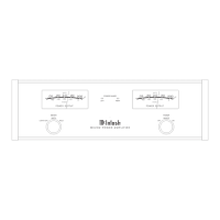
MC275 Stereo Operation Connection Diagram
1A
McIntosh Laboratory, Inc. 2 Chambers Street Binghamton, New York 13903-2699 Phone: 607-723-3512 www.mcintoshlabs.com Part No. 04131300
Audio Preamplifier
Note: Refer to the MC275 Owner’s Manual page 10 for additional connection information.
Connection Legend:
Data Cable*- Digital Signal Cable -
Sensor/Keypad Cable - Network/RS232 Cable -
Power Control Cable* - Ground Wire -
Audio Signal Cable - AC Power Cords -
Video Signal Cable - Loudspeaker Cable -
RF Signal Cable -
* 2 conductor shielded with 1/8 inch stereo mini phone plug on each end.
Connect to
AC Outlet
Right Loudspeaker System Left Loudspeaker System
(-)
(+)8Ω
(-)
(+)8Ω
(+)8Ω
(-)
(+)8Ω
(-)

Other manuals for McIntosh MC275

Questions and Answers:

Question and Answer IconNeed help?

Do you have a question about the McIntosh MC275 and is the answer not in the manual?

McIntosh MC275 Specifications

General IconGeneral
Damping factor20
Amplifier class-
Frequency range10 - 70000 Hz
Output impedance16 Ω
Audio output channels2.0 channels
Peak power per channel75 W
Signal-to-Noise Ratio (SNR)100 dB
Total Harmonic Distortion (THD)0.50 %
RMS power output per channel (2 Ohm)150 W
XLR inYes
Audio (L/R) in2
Audio (L/R) out6
Speakers connectivity typeBinding post
PurposePerformance/stage
Product colorBlack, Silver
Connectivity technologyWired
Maximum current3.6 A
AC input voltage120 V
AC input frequency50 - 60 Hz
Package weight34100 g
Weight and Dimensions IconWeight and Dimensions
Depth304.8 mm
Width419.1 mm
Height209.6 mm
Weight30500 g

Related product manuals