circuit. A soft start is achieved that eliminates component stress during turn-on.
CIRCUIT OPERATION
The audio input passes through the gain control to a preamplifier. The output amplifier
is driven by the preamplifier.
The power output amplifier uses two stages of voltage amplification followed by three stages
of current amplification. All stages are complementary balanced. Even number harmonics
are canceled by the balanced circuits. This means that the amplifying stages have less total
harmonic distortion and less negative feedback is required to achieve ultra low distortion.
The signal is fed to one input of the balanced differential stage. Feedback from the amplifier
output is applied to the other input. The differential amplifiers drive a balanced cascode con-
nected voltage amplifier stage. Current mirrors are also used to improve bandwidth and
linearity.
The cascode voltage amplifier output feeds complementary Darlington connected driver
transistors. These supply the signal to 10 complementary connected output transistors per
channel. Ancillary components for Power Guard, Sentry Monitor, Power Output Meters and
other protection circuits inter connect with the amplifier circuits. The power supply uses a
massive power transformer, full wave bridge rectifiers, and large filter capacitors having 227
joules of energy storage. Four large heatsinks provide cooling for the 20 power output
transistors.
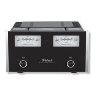
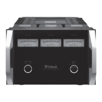
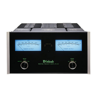
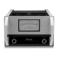
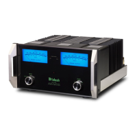
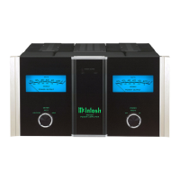
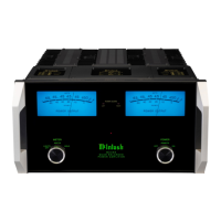
The mechanical and electrical design of the MC300 is the result of the many years of
engineering and manufacturing experience held by the staff at Mclntosh. This "know how",
the meticulous attention to design and production details, makes the MC300 one of the finest
amplifiers ever produced by Mclntosh Laboratory.
17
TECHNICAL
DESCRIPTION
 Loading...