Do you have a question about the McIntosh MC901 and is the answer not in the manual?
Please read all enclosed safety information included in separate documents to ensure user safety.
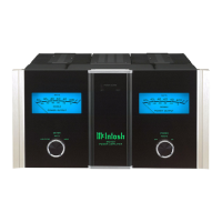
Expresses gratitude for purchase and encourages familiarization with features for maximum performance.
Section to record serial number and purchase information for future reference and identification.
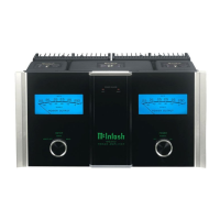
The MC901 is designed for bi-amping, combining Tube and Solid State for optimal loudspeaker performance.
Explains McIntosh's patented technologies for transformer design and solid-state amplification for superior sound.
Details Power Guard for distortion prevention and SGS for protecting vacuum tubes from excessive current.
Lists the items included in the MC901 package, such as the amplifier, manual, and necessary accessories.
Advises on upright installation, proper airflow, and clearance requirements for optimal and safe operation.
Warns about fire hazard and damage if foam inserts are not removed before connecting power to the unit.
Step-by-step instructions to safely remove protective foam from the vacuum tubes before operation.
Details the various input types (Composite, Direct, Balanced, Unbalanced) and their respective connectors.
Describes the switch for selecting DIRECT or COMPOSITE input for the Vacuum Tube amplifier section.
Describes the switch for selecting DIRECT or COMPOSITE input for the Solid State amplifier section.
Explains the Power Control connection for system integration and the Auto Off feature functionality.
Identifies the speaker output terminals for both Vacuum Tube (300W) and Solid State (600W) sections.
Advises connecting the AC power cord last, after all other audio and control connections are made.
Explains how to select between Balanced and Unbalanced inputs using the INPUT MODE switch.
Details how Input Select switches bypass level adjust and filters when DIRECT input is chosen.
Discusses the advantages of Balanced XLR connections over Unbalanced RCA for improved signal integrity.
Explains Composite input for typical use and Direct inputs for external crossovers or specific audio setups.
Describes the Power Control input/output for system On/Off signaling and meter light control.
Explains the automatic power-off function after 30 minutes of no input signal when the feature is enabled.
Guides on selecting the correct 2, 4, or 8 Ohm output terminals based on loudspeaker impedance.
Provides a guide for selecting appropriate speaker wire gauge based on wire length and impedance.
Outlines steps for connecting speaker wire, emphasizing AC power disconnection and polarity.
Instructions on rotating terminal posts to create an opening for speaker wire insertion.
Details on inserting cable and using the McIntosh wrench to securely tighten the output terminals.
Guidance on sliding the terminal connection cover over the terminals for safety and protection.
Crucial instruction to remove jumper cables when connecting Solid State to Low terminals and Tube to High/Mid.
Explains how Sentry Monitor protects the amplifier from impedance mismatches or short circuits.
Provides instructions on how to reset the Sentry Monitor protection circuit if it activates.
Details how Quad Balancing cancels noise while doubling power in both Solid State and Tube amplifier sections.
Explains the function of the circuit breaker and how to reset it if the unit trips.
Shows balanced cable connection from Preamplifier to Composite Input on the MC901.
Illustrates Power Control connections between units for synchronized power on/off operations.
Depicts connecting Solid State to Low terminals and Vacuum Tube to High/Mid terminals on loudspeakers.
Shows the diagrammatic connection of the MC901 to the AC power outlet for operation.
Guides setting the SOLID STATE LOW PASS FILTER for woofer-midrange crossover points (100Hz-1kHz).
Guides setting the VACUUM TUBE HIGH PASS FILTER for midrange-high crossover points (100Hz-1kHz).
Advises matching filters to loudspeaker specifications to avoid peaks or notches in the sound reproduction.
Explains using LEVEL ADJUST knobs for gain adjustments (-6dB to +3dB) for balance between amplifier sections.
Lists the specific vacuum tube types (KT88, 12AT7, 12AX7A) and quantities used in the MC901.
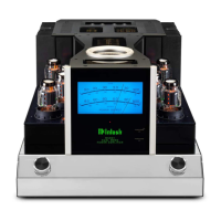
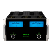
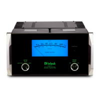
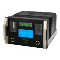
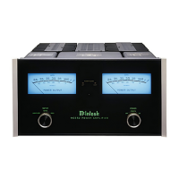
Describes the custom Dual Meter displaying power output for Vacuum Tube and Solid State sections.
Explains the three positions: LIGHTS OFF, WATTS, and HOLD for meter operation and display.
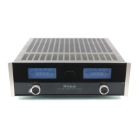
Describes the OFF, REMOTE, and ON positions for controlling the unit's power state.
Explains the red LED indicating Power Guard is engaged for the Solid State amplifier section.
Explains the red LED indicating Power Guard SGS protecting Vacuum Tubes from excessive screen grid current.
Emphasizes packing the unit as originally shipped to prevent damage during transit.
Lists specific packing materials and part numbers required for proper repacking of the unit.
Stresses the importance of attached feet for correct equipment location on the bottom pad during shipping.
Graph showing the roll-off characteristics for various SOLID STATE LOW PASS FILTER settings.
Lists the crossover points (100Hz-1kHz) corresponding to the lines in the low pass filter roll-off graph.
Graph showing the roll-off characteristics for various VACUUM TUBE HIGH PASS FILTER settings.
Lists the crossover points (100Hz-1kHz) corresponding to the lines in the high pass filter roll-off graph.
Graph demonstrating the combined taper for both High Pass and Low Pass filters at a 1kHz crossover point.
Details power output ratings into 2, 4, and 8 Ohm loads for the Solid State amplifier section.
Specifies the frequency response range and tolerances for the Solid State amplifier.
Lists Total Harmonic Distortion and Intermodulation Distortion for the Solid State section.
Details power output ratings into 2, 4, and 8 Ohm loads for the Vacuum Tube amplifier section.
Specifies the frequency response range and tolerances for the Vacuum Tube amplifier.
Lists Total Harmonic Distortion and Intermodulation Distortion for the Vacuum Tube section.
Details input and output voltage/current specifications for the Power Control feature.
Lists power requirements, overall dimensions, and weight of the MC901 unit.
| Type | Hybrid Amplifier |
|---|---|
| Power Output (Solid State) | 300 Watts |
| Total Power Output | 600 Watts |
| Total Harmonic Distortion (Tube Amplifier) | 0.5% |
| Total Harmonic Distortion (Solid State Amplifier) | 0.005% |
| Signal to Noise Ratio (Tube Amplifier) | 112dB |
| Signal to Noise Ratio (Solid State Amplifier) | 120 dB |
| Damping Factor (Solid State Amplifier) | >40 |
| Input Impedance (Balanced) | 20K Ohms |
| Input Impedance (Unbalanced) | 20K Ohms |
| Voltage Gain (Solid State Amplifier) | 26 dB |
| Number of Channels | 1 |
| Speaker Impedance Taps | 2, 4, 8 Ohms |
| Frequency Response | 20Hz - 20kHz |
| Dynamic Headroom (Solid State Amplifier) | 1.8dB |
| Inputs | 1 Balanced, 1 Unbalanced |
| Outputs | Binding Posts |
| Tube Complement | 2 x 12AX7, 2 x 12AT7 |
| Dimensions (W x H x D) | 22.5 inches |
| Rated Power Band | 20Hz - 20kHz |