11
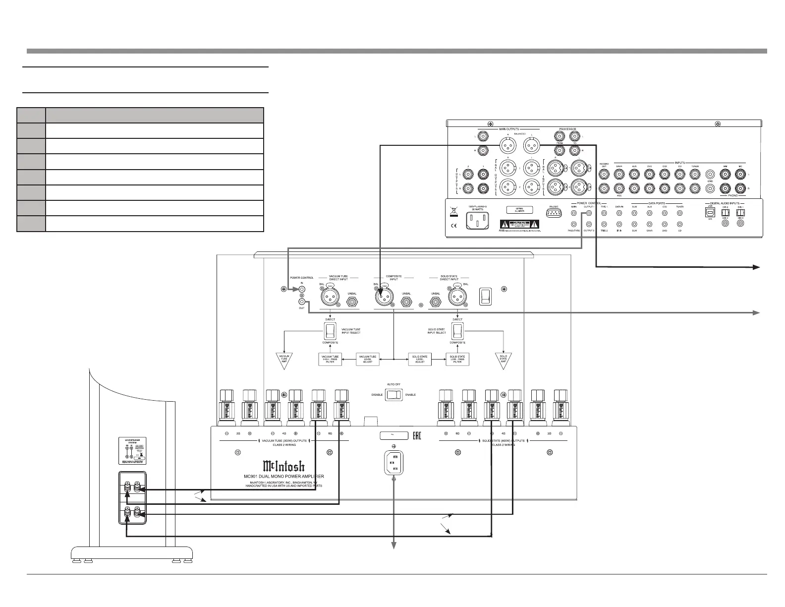
MC901 Connecon Diagram
Audio Preamplifier
INPUT MODE
BALANCED
UNBALANCED
Loudspeaker System
Connect to
–
AC Outlet
+
120V 50/60Hz
12 AMPS
CIRCUIT
BREAKER
Figure 13– MC901 Connection Diagram
# Connection
1
Balanced cable Preamplier to Composite Input
2
Balanced cable to 2nd MC901
3
Power Control from Preamplier OUT to IN
4
Power Control OUT to 2nd MC901 IN
5
Solid State to Low Speaker Terminals
6
Vacuum Tube to High/Mid Terminals
7
To AC Power
#1
#2
#3
#4
#7
#5
#6