12
the cable ends, refer to figures 1, 2 & 3.
If the cable
is stranded,
carefully
twist the
strands to-
gether as tightly as possible.
Notes: 1. If desired, the twisted ends can be tinned
with solder to keep the strands together.
2. The prepared bare wire cable ends may be
inserted into spade lug connectors.
3. Banana plugs are for use in the United
States and Canada only.
Banana Plugs are for use in the United States and
Canada only:
5. Attach the previously prepared bare
wire cable ends into the banana plugs
and secure the connections. Refer to
figure 4.
6. Referring to figure 5, connect the
Loudspeaker hookup cables with
banana plugs into the hole at the end
of the MI254 Negative and Positive
Output Terminals, making sure to
match up channel designation with
Loudspeaker location.
WARNING: Loudspeaker terminals are hazard-
ous live and present a risk of electric
shock. For additional instruction on
making Loudspeaker Connections
contact your McIntosh Dealer or
McIntosh Technical Support.
7. Connect the MI254 power cord to an active AC
outlet.
How to Connect Same Source for Zones B
and C System
be connected in a similar manner. For additional in-
formation refer to “Connector and Cable Information”
on page 3.
1. The Power Control Connection between the MI254
and a Music Streamer provides automatic Power
Control of the MI254.
Note: The AUTO OFF Signal Sensing Circuitry
is automatically activated when there is no
Power Control Cable connected to the MI254
and only Zone C is being used.
2. Connect unbalanced cables from the Music
Streamer Unbalanced Audio Output (Left and
Right Channel) to the MI254 BUS 1 INPUTS,
making sure to match up channel designations.
3. Place the CHANNEL 1/R, 2/L, 3/R and 4/L Input
Selector Switches to the “-1” Position.
This McIntosh MI254 Power Amplifier is designed
for Loudspeakers with an impedance of 4 ohms or
8 ohms. Connect a single Loudspeaker only to each
Channel Output Terminals.
When connecting Loudspeakers to the MI254 it
is very important to use cables of adequate size, so
there is little to no power loss in the cables. The size is
specified in Gauge Numbers or AWG (American Wire
Gauge). The smaller the Gauge number, the larger the
wire size:
Loudspeaker Cable Distance vs Wire Gauge Guide
Loudspeaker
Impedance
25 feet
(7.62 meters)
or less
50 feet
(15.24 meters)
or less
100 feet
(30.48 meters)
or less
4 Ohms
14AWG 12AWG 10AWG
8 Ohms
16AWG 14AWG 12AWG
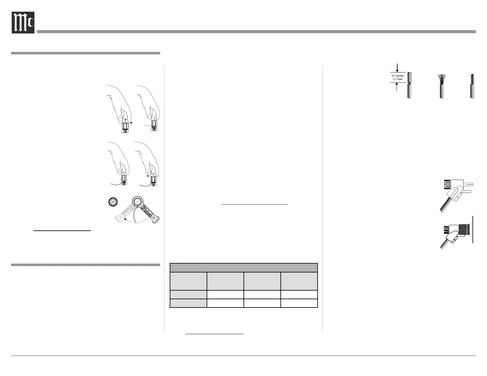
4. Prepare the Loudspeaker Hookup Cable for attach-
ment to the MI254 Power Amplifier:
Bare wire cable ends:
Carefully remove sufficient insulation from
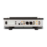
Caution: Do not connect the AC Power Cord to the MI254
Rear Panel until after the Loudspeaker Connec-
tions are made and the protective Terminal Con-
nections Cover is installed. Failure to observe
this could result in Electric Shock.
The connection instructions below, together with the
MI254 Connection Diagram located on the separate
folded sheet “Mc1C”, is an example of Same Source
for a Zone B and Zone C System. Your system may
vary from this, however the actual components would
Figure 1
Figure 2 Figure 3
Figure 5
Figure 4
Output Terminals
When connecting the Loudspeaker Hookup Cables to
the MI254 Amplifier Output Terminals please follow
the steps below:
1. Rotate the top of the Output Terminal Post coun-
terclockwise until an opening
appears. Refer to gures A and
B.
2. Insert the Loudspeaker hookup
cable into the Output Terminal
Post opening or the cable spade
lug around the center post of
the Output Terminal. Refer to
gure C.
3. Rotate the top of the Output
Terminal Post clockwise until it
is nger tight. Refer to gure D.
4. Place the supplied McIntosh
Wrench over the top of the Out-
put Terminal and rotate it one
quarter of a turn (90°) to secure
the Loudspeaker Cable Connec-
tion. Do not over tighten. Refer
to gure E.
Figure A
Opening
Figure B
Figure C Figure D
Figure E
 Loading...