6
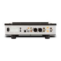
Rear Panel Connections and Switches
Connect the MI254
Power Cord to a live
AC Outlet
Main Fuse, refer to the
Rear Panel for the correct
fuse size and rating
CHANNEL 4/Left Output
Connections for a 4 ohm
or 8 ohm Loudspeaker
UNBALanced Input
CHANNEL 4/Left
PWR CNTRL (Power Control)
IN receives turn On/Off signal
from a McIntosh component.
PWR CNTRL (Power Control)
OUT sends a turn On/Off signal
to another McIntosh Component
UNBALanced Input
CHANNEL 3/Right
UNBALanced Input
CHANNEL 2/Left
UNBALanced Input
CHANNEL 1/Right
CHANNEL 4/Left
Input Selector Switch
1
CHANNEL 3/Right
Input Selector Switch
1
CHANNEL 2/Left
Input Selector Switch
1
CHANNEL 1/Right
Input Selector Switch
1
BALanced Input
CHANNEL 4/Left
BALanced Input
CHANNEL 3/Right
BALanced Input
CHANNEL 2/Left
BALanced Input CHAN-
NEL 1/Right
CHANNEL 3/Right Output
Connections for a 4 ohm or
8 ohm Loudspeaker
CHANNEL 2/Left Output
Connections for a 4 ohm or
8 ohm Loudspeaker
CHANNEL 1/Right Output
Connections for a 4 ohm or
8 ohm Loudspeaker
BUS 1 Left and Right INput and
OUTput Connections
1
Jacks
BUS 2 Left and Right INput and
OUTput Connections
1
Jacks
1
Refer to page 7 for detailed information about utilization of the CHANNEL 1-4 Input Switches and the functioning of the BUS 1-2 INput and OUTput connection jacks
 Loading...