IOMM AGR AGR 055A through 100A 49
Digital Inputs
Note: All Digital Inputs are 24 VAC supplied by transformer T2 in the control panel. Do not
use inputs from another power supply external to the unit. This can cause failure of the
Global UNT controller.
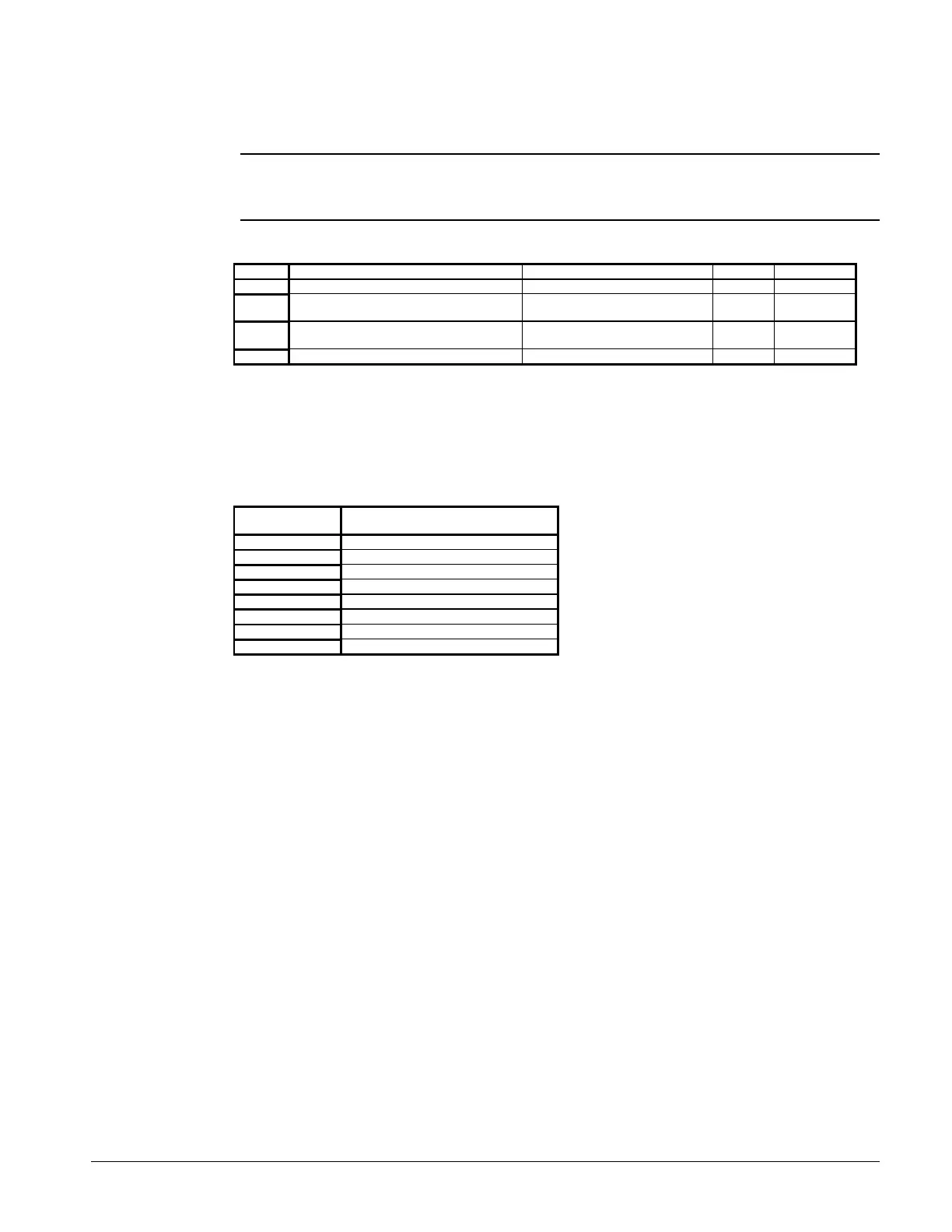
Table 14, Digital Inputs
Input Description Location Closed Open
BI-1 Time Clock Field Installed to TB-7 #140 & #141 Run Stop
BI-2 Auto / Pumpdown and Stop Switch Circuit #1 Control Panel Run Pumpdown
Stop
BI-3 Auto / Pumpdown and Stop Switch Circuit #2 Control Panel Run Pumpdown
Stop
BI-4 Chilled Water Flow Switch Field Installed to TB-7 #142 & #143 Run Stop
Relay Outputs
All of the relay outputs are controlled by the Global UNT controller. The relays are double pole
double throw relays with contacts rated for 120VAC - 7.0 amp and a 24 VAC holding coil. Refer to
the unit staging schematic.
Table 15, Relay Board Outputs
Relay Output
Number
Output
Description
1 Circuit #1 Liquid Line Solenoid Valve
2 Circuit #2 Liquid Line Solenoid Valve
3 Compressor #1 Unloader #1
4 Compressor #2 Unloader #1
5 Compressor #1 Unloader #2 (6-stage)
6 Compressor #2 Unloader #2 (6-stage)
7 Low Pressure Relay Circuit #1
8 Low Pressure Relay Circuit #2
Reset Options
The Global UNT controller is capable of one reset option. The reset option should be selected at the
time of purchase. Outside Air is the standard option and a Zone Terminal is necessary to activate
this option or any other reset option. Other reset options are available and requires a software
download. Field modifications can be accomplished with the Global UNT Interface Kit.
Outside Air Reset
When selected, a Outdoor Air Temperature (OAT) sensor is connected to TB-7 terminals #134 and
#135. Four variables are used to setup the reset ramp that calculates the Actual Leaving Water
Setpoint. These are: Leaving Water Setpoint (AI-4), Reset Band selected with a Zone Terminal,
Outdoor Air High Limit (OAHL), and Outdoor Air Reset Band (OARB).
 Loading...


