IOMM AGR AGR 055A through 100A 75
rises above the LPCutIn value, a compressor on the lead circuit will start. Refer to the unit staging
schematic to determine which LED is associate to a compressor.
The controller will stage up and down to maintain the desired leaving water temperature.
Temporary Shutdown
Close both pumpdown switches. After pumpdown is completed, turn off the system switch. Open
the remote start / stop input and the evaporator pump will stop. Perform the reverse to start up after
a temporary shutdown.
Extended Shutdown
CAUTION
The operator must provide protection against water circuit freezing on all chiller units. All
water must be drained form the evaporator and associated piping and power for the cooler
heating cable should be applied via separate disconnect if freezing ambient conditions are
expected.
1. Close the manual liquid line shut off valves. Move the circuit #1 and #2 switches to the
“Pumpdown and Stop” position. Each operating circuit will pumpdown and the compressors
will stop.
2. After both circuits have been pumped down, open the “Remote Start / Stop’ input and the
controller will open output relay #1 to stop the evaporator pump.
3. Move the system switch to the stop position. Turn off main power to the chiller unit and to the
chilled water pump.
4. Tag all open electrical switches and related water valves. This will prevent premature operation
of the equipment.
5. If the chiller will be exposed to freezing ambient temperatures, drain all water from the unit
evaporator and chilled water piping and leave power applied to the evaporator heating cable via
separate disconnect. If external water piping is heat traced, leave power on to heat tracing to
protect from freezing.
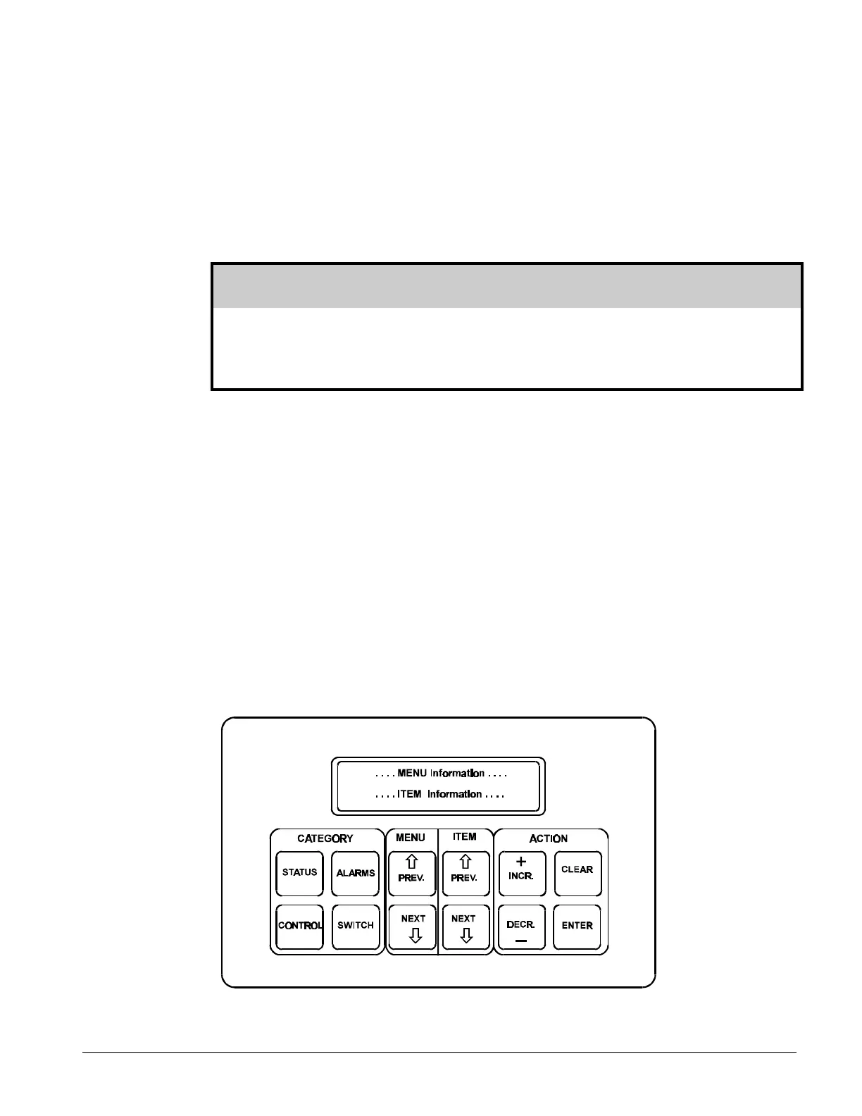
Keypad / Display
Figure 34, Keypad / Display
 Loading...


