90 AGR 055A through 100A IOMM AGR
Following is the normal start-up sequence that the three status LED’s should follow when
power is applied to the MCB:
1. The red (“Reset”) LED turns on and remains on for approximately 5 seconds. During this
period the MCB performs a self-test.
2. The red LED turns off and the green (“Running”) LED turns on. This indicates that the
microprocessor has passed the self-test and is functioning properly.
3. The amber (“Active”) LED remains off continually if no alarm conditions exist in the network.
If alarm conditions exist, the amber LED will flash as shown in Table 54.
If the above sequence does not occur after power is applied to the controller, there is a problem
with the MCB or its power supply.
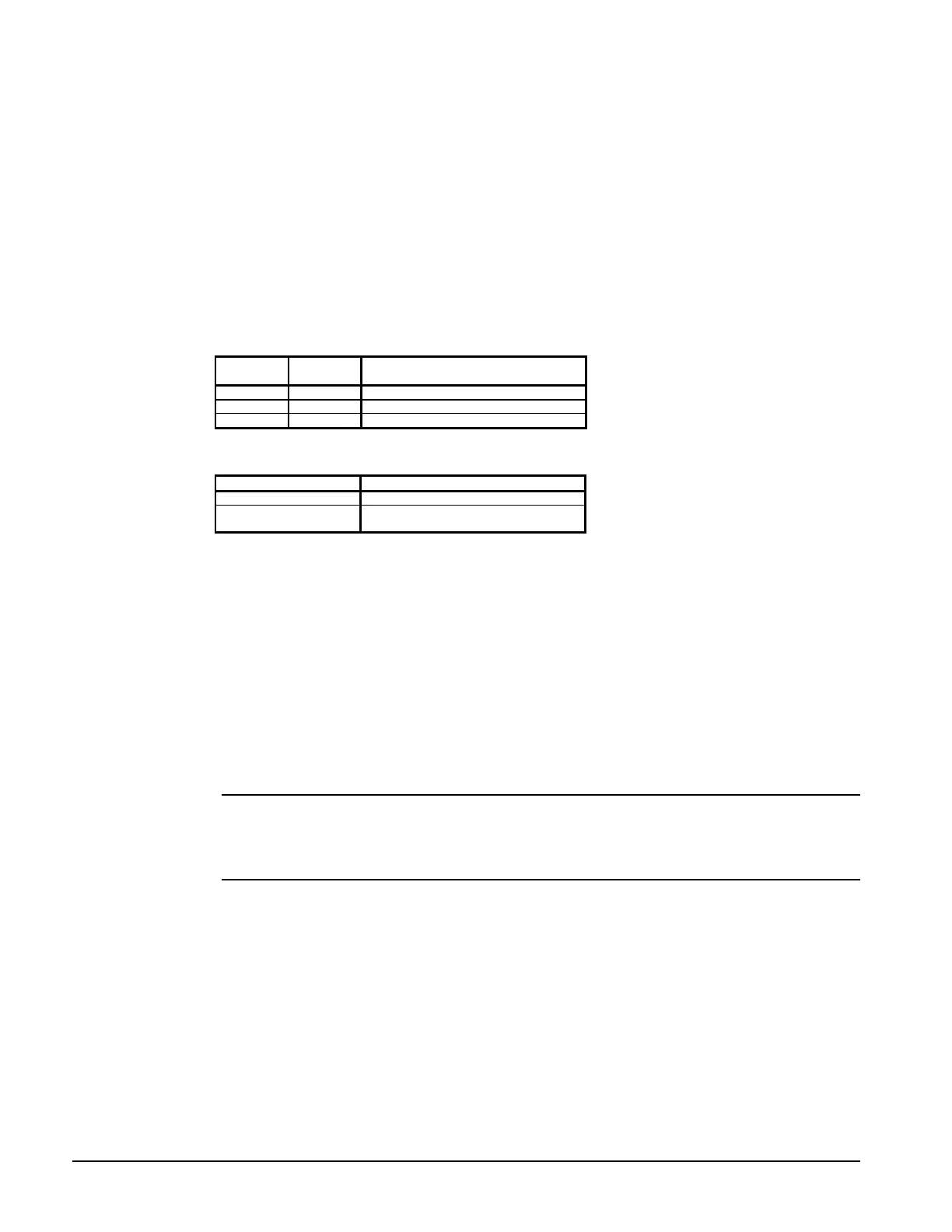
Table 53 and Table 54 summarize the green, red, and amber status LED indications.
Table 53, Green and Red Status LED Indication
Green
LED State
Red
LED State Indication
Off Off No power to MCB
Off On* Self-test failure or power supply problem
On Off MCB operating normally
* For longer than 5 seconds.
Table 54, Amber Status LED Indication
Amber LED State Indication
Off Normal operation
On 1/2 second;
Off 1/2 second Alarm condition
Keypad/LCD Display Connection
The MCB receives input commands and operating parameters from the keypad and sends requested
information to the display through the Keypad/LCD Display port via a plug-in ribbon cable.
Hex Switches
The MCB includes two hex (hexadecimal) switches that are used to set the network address.
The HI and LO hex switches are shown in Figure 37. A “hex switch setting” is defined as the
HI switch digit followed by the LO switch digit. For example, a hex switch setting of 2F would have
the HI switch set to “2” and the LO switch set to “F.”
Note: You can change the setting of a hex switch with a 3/32-inch tip slotted-blade
screwdriver. If a hex switch setting is changed, power to the MCB must be cycled in order
to enter the new setting into memory. This can be done by turning the panel’s power switch
off and then back on.
 Loading...


