McQuay IM 660-3 5
Interface Features
MicroTech Network
Control sequencing, stop/start, equipment protection
monitoring, and fault resets can be accomplished through a
network connection. The following unique values and
parameters can be accessed for each unit (refer to Protocol
Document ED15054 for more information):
• Return air and discharge air temperatures
• Compressor, fan and reversing valve status
• High pressure, low temperature, brownout and drain pan
status
• Occupied and unoccupied heat and cool set points
• Auto/manual and occupied/unoccupied fan control
• Mode, fault, system, schedule and set point operation
• Compressor starts and fan run hours
• Load shed level (L
ONWORKS only)
• Tenant override status
In addition, the following unique operation and maintenance
parameters can display for each unit:
• Leaving water temperature
• Return air temperature set point (wall sensor adjustment)
• Adaptive optimal start (L
ONWORKS only)
• Occupied/unoccupied (on/cycle) fan mode
• Room temperature warning
• Filter changes from fan hours
• Compressor management: on/off differential, minimum off
time, minimum on time
Communications Failure (L
ONWORKS): If the network
communication link fails for any reason, the affected WSHP
controller remains operational. Its operating mode will be the
last received over the network unless power is cycled, and then
it defaults to occupied. Its minimum position, heating, and
cooling set points will be those last received over the network,
regardless of whether power is cycled.
Communications Failure (L
ON
M
ARK
):
If the network
communication link fails for any reason, the affected WSHP
controller remains operational. The status of its heating and
cooling set points as well as its occupancy and other network
adjustable settings depends upon whether the BAS is using
LONWORKS
bindings with associated heartbeats.
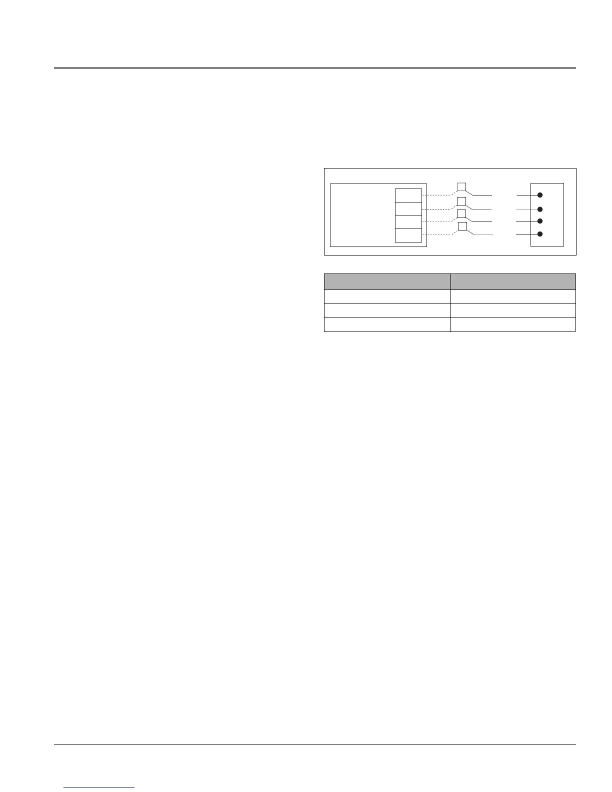
Wall-Mounted Sensor
There are four optional wall sensor packages available. All
include a remote status LED and tenant override button. Set
point adjustment and thermometer are optional features.
The wall-mounted sensor must be field installed and field
wired to the water source heat pump. Terminal Board #1
provides the connections for all room temperature sensor field
wiring. Refer to the unit wiring diagram provided and to IM
529, MicroTech Room Temperature Sensors, for information
on wall sensor package installation.
Figure 5: Wall-mounted temp sensor wiring
Remote Room Set Point Adjustment
The remote set point adjustment potentiometer allows the room
set point to be adjusted up or down by as much as 3°F (1.7°C).
It is available with several of the optional wall sensor packages.
Tenant Override
A wall-mounted tenant override switch is standard on all McQuay
MicroTech Room Temperature Sensors. Pressing and holding the
tenant override button for 1.0 to 6.0 seconds puts the unit into
tenant override mode for a set time period (default = 60 minutes).
Press the tenant override button again for 1.0 to 6.0 seconds and
the unit returns to unoccupied mode by default. A separate
configuration property is available that allows users to extend the
tenant override period for up to 60 minutes with a second button
press. Except for the fact that it is temporary, the tenant override
operating mode is identical to the occupied operating mode.
LONWORKS only: Pressing and holding the tenant override
button for at least 6 seconds but not more than 10 seconds
activates the network “query address” mode, indicating the
unit address in question at the MicroTech gateway panel.
L
ONWORKS only: Pressing and holding the tenant override
button more than 10 seconds activates the network
“self-configure” mode, requesting the assignment of the next
sequential address from the MicroTech gateway panel.
L
ONMARK only: Similar to pressing the service pin, pressing
and holding the tenant override button for more than 10
seconds causes the Neuron chip to broadcast a message over
the L
ONWORKS network containing its unique 48-bit Neuron
ID. This is useful during network commissioning.
Table 4: Maximum wire length to sensors
Gauge Length (ft.)
18 AWG 625
20 AWG 380
22 AWG 260
WSHP Wall sensor
Sensor LED
Tenant override
Sensor input
Sensor common
Red
Green
White
Black
TB1-1
TB1-4
TB1-3
TB1-2