EasyManua.ls Logo

McQuay TSC

McQuay TSC
100 pages
To Next Page IconTo Next Page
Loading...
Operating Manual
OM CentrifMicro II-5
Group: Chiller
Part Number: 331374901
Effective: March 2011
Supersedes: November 2010
MicroTech Ι
ΙΙ
ΙΙ
ΙΙ
Ι
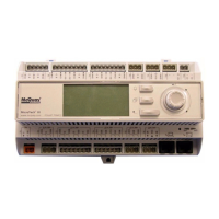
Controller
With Starter Information
For Centrifugal Chillers and Templifiers
Models WSC, WDC, WCC, HSC, TSC
Software Version: WCFU3UU04C/D/E
OITS Version: 2.05.03

Questions and Answers:

McQuay TSC Specifications

General IconGeneral
BrandMcQuay
ModelTSC
CategoryController
LanguageEnglish

Summary

Features of the Control Panel

General Description

Component Description

Unit Controller

Compressor Controller

Field Wiring Diagram

DualMulti-Chiller Operation

Multiple Chiller Setup

Describes interconnecting up to four chillers via pLAN.

pLAN Setup

Details RS485 wiring and configuration for multi-chiller setup.

Communication Wiring

MicroTech II Operator Interface Touch Screen (OITS) Settings

Maximum Compressors ON

Sets the maximum number of compressors allowed to run.

Sequence and Staging

Defines the sequence in which compressors will start and stage.

Nominal Capacity

Sets the compressor design tons.

Operating Sequence

Operator Interface Touch Screen

SET Screens

Editing Setpoints

Details the process for accessing and changing setpoints.

Typical SETPOINT Screen

Procedure for Changing a Setpoint

Details the step-by-step process for modifying setpoint values.

Explanation of Setpoints

TIMERS

For setting timers like start-to-start, prelube, and postlube.

ALARMS

For setting limit and shutdown alarms.

VALVE

For tower bypass valve operation parameters.

TOWER

For cooling tower fan control and parameters.

MOTOR

For motor-related setpoints like amp limits.

MODES

For selecting operating modes and staging.

WATER

For leaving water temp, delta-T, and resets.

STARTER SETPOINTS

Optional Starter Setpoint Screen

Displays and allows setting of starter-specific parameters.

TIMERS Setpoint

TIMERS Setpoint Screen

Allows adjustment of various timing parameters for operation.

ALARMS Setpoint

ALARMS Setpoint Screen

Allows configuration of alarm limits and shutdown conditions.

Cooling Tower Bypass Valve Settings

Tower Bypass Valve Setpoint Screen

Configures parameters for the cooling tower bypass valve operation.

Cooling TOWER Fan Settings

Cooling TOWER Fan Setpoint Screen

Sets parameters for cooling tower fan staging based on temperature or lift.

Explaination of Tower Control Settings

Tower Fan Staging Only (NONE)

Configuration for tower fan staging without bypass valve or VFD control.

Tower Fan Staging With Bypass Valve Controlling Minimum EWT (VALVE SP)

TOWER SETPOINT Screen

Setpoints for tower fan staging with bypass valve controlling minimum EWT.

VALVE SETPOINT Screen

Setpoints for valve control in this mode.

Tower Staging with Bypass Valve Controlled by Fan Stage (VALVE STAGE)

Fan VFD, No Bypass Valve (VFD STAGE)

MOTOR Setpoint Screen

MOTOR Setpoint Screen

Configures motor parameters like FLA, speed, and limits.

MODES Setpoints

MODES Setpoint Screen

Selects operating modes, compressor staging, and control sources.

WATER Setpoints

WATER Setpoint Screen

Configures water temperature setpoints and reset parameters.

SERVICE Screen

Service Screen

Provides access to unit status, versions, and maintenance functions.

ACTIVE ALARM Screen

Active Alarms Screen

Displays current active alarms with date, time, and cause.

Fault Alarms

Problem Alarms

Warning Alarms

Set Screens

Unit and Compressor Setpoints

Configuration of unit and compressor parameters like mode, staging, and limits.

Alarm and Tower Setpoints

Configuration of alarm limits and cooling tower control settings.

View ALARM Screens

Active Alarm Screen

Shows currently active, uncleared alarms.

Editing Setpoints

Unit Controller Setpoints

Table 23, Unit Setpoints

Comprehensive list of unit controller setpoints, defaults, and ranges.

EXV Control Parameters

Set Compressor Setpoints

Staging Parameters

Set Alarm Setpoints

Set Tower Setpoints

Alarms

Compressor Controller Setpoints

Table 24, Compressor Setpoints

Compressor Setpoints

Low Voltage Starters, 200 - 600 Volts

Solid State Starter Overview

Operation

Restoring Factory Parameter Settings

Faults and Alarms

Alarm Definitions

Troubleshooting

Fault Code

Preventive Maintenance

MediumHigh Voltage Starters, 2300 V - 7.2 KV

View Parameters

Set Parameters

Menu Structure

Quick Start

Max. Curr. (maximum current)

Ramp Time

Overload

Phase Order

FaultLog Codes

Sequence of Operation

Determining Full Load Status

Full Load Determination

Defines conditions for a compressor reaching full load status.

Operating the Chiller Control System

Change Setpoints

Component Failure

Standby Power

Maintenance Schedule

I. Unit

Unit-specific maintenance tasks including logs and leak tests.

II. Compressor

Compressor maintenance tasks, including motor and lubrication.

III. Controls

Maintenance for operating and protective control systems.

Maintenance Schedule, Cont.

IV. Condenser

Condenser maintenance including tube cleaning and temp approach.

V. Evaporator

Evaporator maintenance including tube cleaning and temp approach.

VII. Starter(s)

Starter inspection, overload verification, and electrical connection checks.

Related product manuals