OM Centrif Micro ΙΙ-5 29
Cooling Tower Bypass VALVE Settings
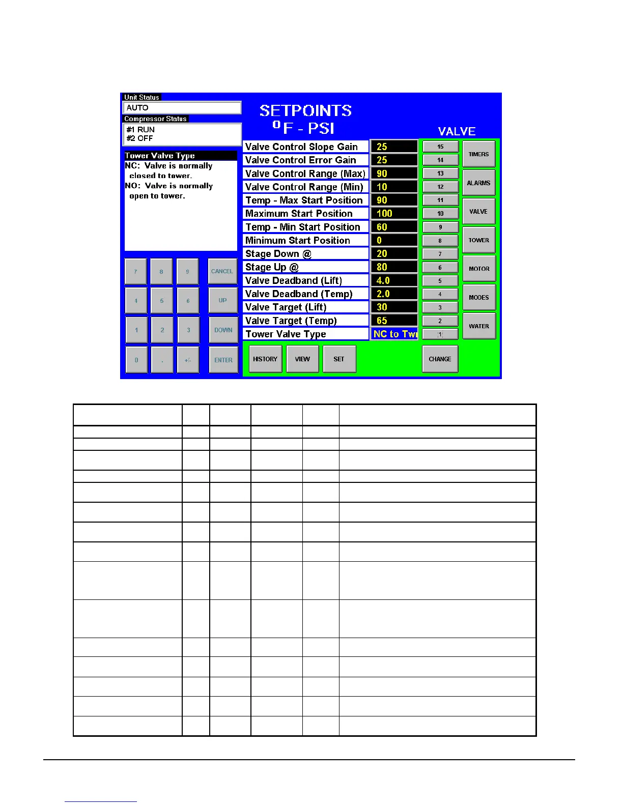
Figure 17, Tower Bypass VALVE Setpoint Screen
Table 15, Tower Bypass VALVE Setpoints (See page 31 for complete explanation.)
Description No. Default Range
Pass-
word
Comments
Slope Gain 15 25 10 to 99 M Control gain for temperature (or lift) slope
Error Gain 14 25 10 to 99 M Control gain for temperature (or lift) error
Valve Control Range(Max) 13 100% 0 to 100% M
Maximum valve position, overrides all other
settings
Valve Control Range (Min) 12 10% 0 to 100% M Minimum valve position, overrides all other settings
Temp - Maximum Position 11
90 °F 0 to 100 °F
M
Condenser EWT at which valve should be open to
tower
Maximum Start Position 10 100% 0 to 100% M
Initial valve position when condenser EWT is at or
above Setpoint # 9
Temp - Minimum Position 9
60 °F 0 to 100 °F
M
Condenser EWT at which initial valve position is
set to Setpoint # 6
Minimum Start Position 8 10% 0 to 100% M
Initial position of valve when condenser EWT is at
or below Setpoint # 7
Stage Down @ 7 20% 0 to 100% M
Valve position below which the fans can stage
down (Tower Setpoint #2 = Valve Stage Down
VFD speed below which the next fan speed can
turn off (Tower Setpoint # 2 = valve/VFD ????
Stage Up @ 6 80% 0 to 100% M
Valve position above which the fans can stage up
(Tower Setpoint #2 = Valve Stage Down
VFD speed above which the next fan speed can
turn on (Tower Setpoint # 2 = valve/VFD ????
Valve Deadband (Lift) 5 4.0 psi
1.0 to 20.0
psi
M Control deadband, Tower Setpoint #1=Lift
Valve Deadband (Temp) 4
2.0 °F
1.0 to 10.0
°F
M Control deadband, Tower Setpoint #1=Temp
Valve Target (Lift) 3 30 psi
10 to 130
psi
M
Target for lift pressure (Tower Setpoint #1= Lift),
Works with Setpoint # 5
Valve Setpoint (Temp) 2
65 °F
40 to 120
°F
M
Target for condenser EWT (Tower Setpoint #1=
Temp), Works with Setpoint # 4
Valve Type 1
NC (To
Tower)
NC, NO M Normally closed or normal open to tower