30 OM Centrif Micro ΙΙ-5
Cooling TOWER Fan Settings
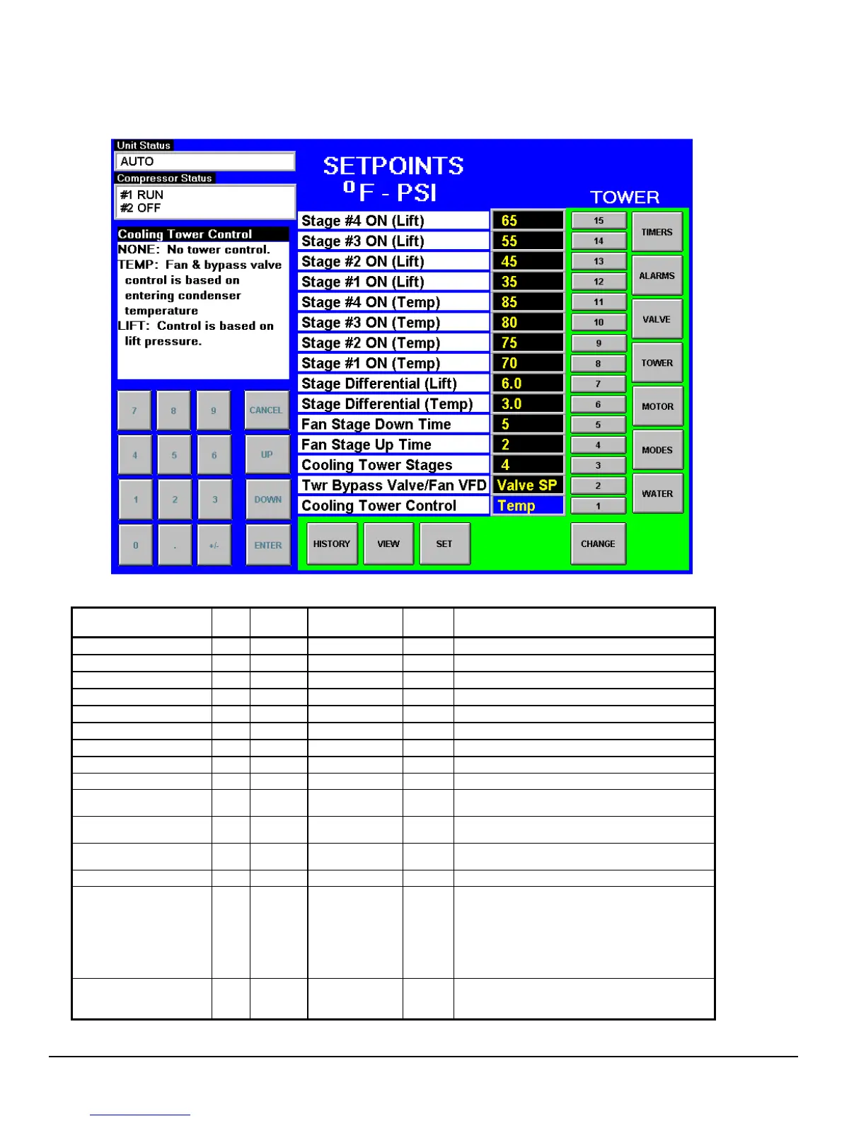
Figure 18, Cooling TOWER Fan Setpoint Screen (See page 31 for complete explanation.)
Table 16, Tower Fan Settings
Description No. Default Range
Pass-
word
Comments
Stage #4 On (Lift) 15 65 psi 10 to 130 psi M Lift pressure for fan stage #4 on
Stage #3 On (Lift) 14 55 psi 10 to 130 psi M Lift pressure for fan stage #3 on
Stage #2 On (Lift) 13 45 psi 10 to 130 psi M Lift pressure for fan stage #2 on
Stage #1 On (Lift) 12 35 psi 10 to 130 psi M Lift pressure for fan stage #1 on
Stage #4 On (Temp) 11
85 °F 40 to 120 °F
M Temperature for fan stage #4 on
Stage #3 On (Temp) 10
80 °F 40 to 120 °F
M Temperature for fan stage #3 on
Stage #2 On (Temp) 9
75 °F 40 to 120 °F
M Temperature for fan stage #2 on
Stage #1 On (Temp) 8
70 °F 40 to 120 °F
M Temperature for fan stage #1 on
Stage Differential (Lift) 7 6.0 psi 1.0 to 20.0 psi M Fan staging deadband with Setpoint # 1=Lift
Stage Differential
(Temp)
6
3.0 °F 1.0 to 10.0 °F
M Fan staging deadband with Setpoint #1=Temp
Stage Down Time 5 5 min 1 to 60 min M
Time delay between stage up/down event and
next stage down
Stage Up Time 4 2 min 1 to 60 min M
Time delay between stage up/down event and
next stage up
Tower Stages 3 2 1 to 4 M Number of fan stages used
Valve/VFD Control 2 None
None, Valve
Setpoint, Valve
Stage, VFD
Stage, Valve
SP/VFD Stage
M
None: No tower valve or VFD
Valve Setpoint: Valve controls to VALVE SP3(4)
& 5(6)
Valve Stage: Valve control setpoint changes to
fan stage setpoint
VFD Stage: 1
st
fan is VFD controlled, no valve
Valve Setpoint/VFD Stage: Both valve and VFD
Tower Control 1 None
None,
Temperature,
Lift
M
None: No tower fan control
Temperature: Fan and valve controlled by EWT
Lift: Fan and valve controlled by lift pressure