EasyManua.ls Logo

McQuay WSC User Manual

McQuay WSC
100 pages
To Next Page IconTo Next Page
Page #1 background imageLoading...
Page #1 background image
Operating Manual
OM CentrifMicro II-5
Group: Chiller
Part Number: 331374901
Effective: March 2011
Supersedes: November 2010
MicroTech Ι
ΙΙ
ΙΙ
ΙΙ
Ι
Controller
With Starter Information
For Centrifugal Chillers and Templifiers
Models WSC, WDC, WCC, HSC, TSC
Software Version: WCFU3UU04C/D/E
OITS Version: 2.05.03

Other manuals for McQuay WSC

Questions and Answers:

McQuay WSC Specifications

General IconGeneral
Control Featuresalarm monitoring
Communication ProtocolBACnet, Modbus
Power Supply24 VAC
Operating Temperature Range0 to 50°C (32 to 122°F)
CompatibilityMcQuay water source heat pumps

Summary

MicroTech IITM Controller With Starter Information

Introduction

Software and Environmental Specifications

Details the software version and operating temperature/humidity limits.

Features of the Control Panel

General Description

Control Architecture

Illustrates major control components and their interconnections.

Component Description

Operator Interface & Controller Details

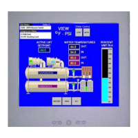
Describes the touch screen interface, controller hardware, and keypad.

Software and Controller Details

Compressor Controller Details

Component Boards and Interfaces

Guardister ew{TM} Board

Monitors motor winding temperature via embedded sensors.

Signal Converter Board

Converts AC current signals to DC for compressor controller.

Transducer Converter Board

Converts pressure transducer signals for the compressor controller.

PLAN Isolator

Provides voltage isolation for pLAN communication between chillers.

Field Wiring Diagram Notes

Dual/Multi-Chiller Operation

Chiller Interconnection and pLAN Setup

Details multiple chiller setup and pLAN communication configuration.

MicroTech II OITS and Operating Sequence

WCC Settings

Specific settings for WCC units concerning compressor staging.

Ice Mode Operation and OITS Navigation

Screen Descriptions

View Screens Overview

Describes how to view unit status and conditions, including the home screen.

Detail View Screen and Menu Navigation

Expanded View Screens and Menu Access

SET Screens Overview

Setpoint Configuration Procedure

Setpoint Explanation

Starter Setpoints

Timer Setpoints

Alarm Setpoints

Cooling Tower Bypass Valve Settings

Cooling Tower Fan Settings

Tower Control Settings Explanation

Tower Fan Staging Options

Details settings for different tower fan staging modes (NONE, VALVE SP, VALVE STAGE).

Tower Control Strategies

VALVE SP and VALVE SETPOINT Screens

Details setpoints for valve control based on temperature or lift.

Advanced Tower Control Strategies

MOTOR Setpoint Screen

MODES Setpoints

WATER Setpoints

SERVICE Screen Overview

HISTORY Screens Functionality

Alarm and USB Data Transfer

ACTIVE ALARM Screen Details

Fault Alarms Explained

Problem and Warning Alarms

Unit Controller Operation and Navigation

4x20 Display & Keypad

Details the display and keypad layout of the unit controller.

Controller Navigation Basics

Explains how to navigate through the controller's menu system.

Screen Navigation and Content

Set Screens Introduction

Viewing Unit Status

View Unit Water Data

Displays water temperature and flow rate data.

Viewing Unit System Data

View Unit Refrigerant and Tower Status

Displays refrigerant pressures and tower fan/control status.

View Compressor Data

Displays operational data for individual compressors.

Compressor Data Views

Compressor Pressure, Temperature, and Status Views

Shows compressor pressure, temperature, and status data in multiple views.

Evaporator and Condenser Data Views

Displays evaporator and condenser approach and subcooling data.

Alarm Screen Access and Setpoint Editing

Alarm Screen Navigation

Accesses alarm logs and active alarm screens.

Setpoint Editing Procedure

Details the process for changing setpoints, including password entry.

Unit Controller Setpoint Configuration

Unit Setpoint Categories (1-4)

Unit Setpoint Categories (5-11)

Unit Setpoint Categories (12-15)

Compressor Setpoint Configuration (1-2)

Demand Limit and Staging Settings

Sets demand limit, staging mode, sequence, and max compressors.

Compressor Setpoint Configuration (3-8)

Staging Parameters Explained

Full Load and Capacity Determination

Explains full load status, absolute capacity, and staging logic.

Alarm and Tower Setpoint Configuration

Tower Control Modes and Settings

Explains tower control strategies and associated setpoint screens.

Tower Setpoint Details

Alarm Handling and Security Access

Security Access Procedures

Details password entry for unit controller and OITS.

Compressor Controller Overview

Controller Display and Navigation

Details the controller's display, keypad, and menu navigation.

Menu Screens and Compressor Setpoints

Compressor Setpoint Configuration

Guides on configuring compressor setpoints.

Compressor Setpoint Reference

Compressor Setpoint Configuration (1-4)

Compressor Setpoint Configuration (5-8)

Staging Parameters Explained

Full Load and Capacity Determination

Explains full load status, absolute capacity, and staging logic.

Optional Starter Screens

Low Voltage Starters Overview

Starter General Description

Describes the automatic nature and function of these starters.

Starter LED Display Functionality

Starter Operation and Programming

Starter Display and Programming Features

Covers LED display, programming, quick meters, and fault log access.

Parameter and Fault Management

Details viewing, resetting parameters, and emergency thermal reset.

Starter Status Messages

Starter Display Messages and Utilities

Starter Display Message Types

Covers power up, stopped, alarm, lockout, faulted, and quick meter messages.

Starter Meter Functions and Troubleshooting

Faults and Alarms Overview

Lists fault and alarm codes for the starter.

Alarm Code Definitions

Starter Troubleshooting and Analog Output

Troubleshooting Common Issues

Guides on diagnosing and resolving starter problems.

Starter Troubleshooting Charts

Fault Code Troubleshooting Table

Preventive Maintenance for Starters

Starter Maintenance Schedule

Lists maintenance tasks by frequency.

Medium/High Voltage Starters

Starter Parameters and Menu Navigation

Guides on viewing and setting starter parameters via menu.

Starter Parameter and Menu Access

Micro II Control Menu Structure

Parameter Changing Procedure

Step-by-step guide to changing a parameter with an example.

Quick Start Configuration Parameters

Motor FLA, Service Factor, and Start/Stop Modes

Setting motor FLA, service factor, and start/stop modes.

Initial Current Settings

Setting the initial current percentage of motor FLA.

Maximum Current and Ramp Time Settings

Phase Order and Troubleshooting Charts

Fault and Log Codes Reference

LED Diagnostics and Maintenance

Starter Maintenance Schedule

Lists maintenance tasks by frequency.

Sequence of Operation

Chiller and Compressor Sequencing

Details chiller starting and compressor staging logic.

Full Load and Capacity Determination

Operating the Chiller Control System

Interface Panel and Unit Control Methods

Covers panel power, start/stop methods (local, remote, BAS, panel switches).

Setpoint Changes, Alarms, and Component Failure

Standby Power Guidelines

Guidelines for connecting the chiller to standby power.

Maintenance Schedule Overview

Unit, Compressor, and Control Maintenance

Covers daily, weekly, and quarterly checks for unit, compressor, and controls.

Maintenance Schedule Continuation

Component-Specific Maintenance Tasks

Details maintenance tasks for condenser, evaporator, expansion valves, starters, and optional controls.

Related product manuals