OM Centrif Micro ΙΙ-5 9
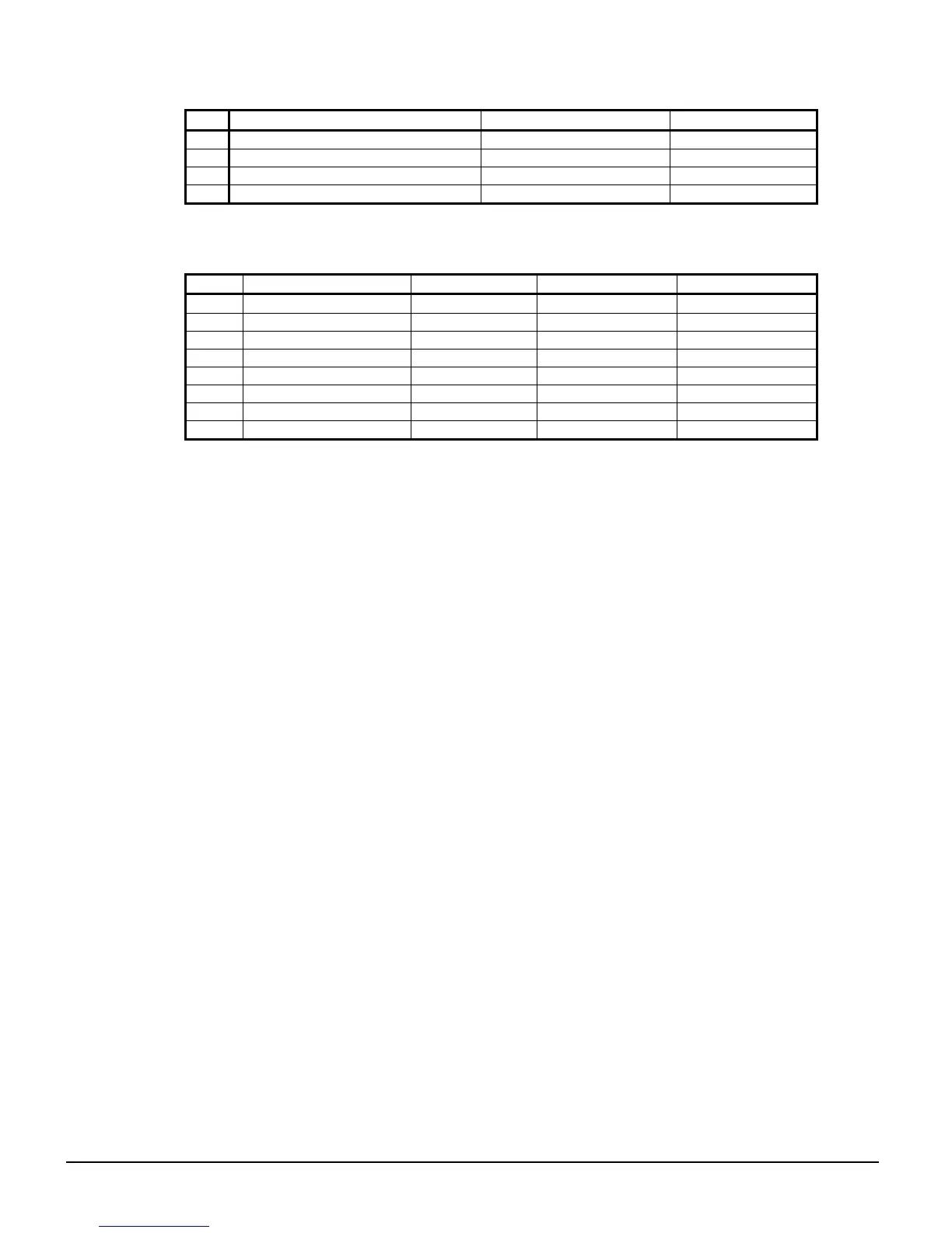
Table 7, Compressor Controller, Analog Outputs
# Description Output Signal Range
Y1
Compressor VFD Speed 0 to 10 VDC 0 to 100%
Y2
Open
Y3
Oil Cooler 0 to 10 VDC 0 to 100%
Y4
Hot Gas Bypass 0 to 10 VDC 0 to 100%
Table 8, Compressor Controller, Digital Outputs
# Description Load Output OFF Output ON
NO1
Motor Control Relay Starter Compressor OFF Compressor ON
NO2
Hot Gas Bypass Solenoid No Bypass Bypass
NO3
Liquid Injection Solenoid No Injection Injection
NO4
Oil Pump Pump Contactor Pump OFF Pump ON
NO5
Oil Sump Heater Heater Heater OFF Heater ON
NO6
Oil Cooler Solenoid Cooling OFF Cooling ON
NO7
Vane Pulse Solenoid Hold Move Vanes
NO/C8
Load/Unload Solenoid Unload Load
Guardister
Board
The Guardister board monitors the motor winding temperature through embedded Guardistor
temperature sensors in the motor. If the motor temperature rises to an unsafe level, the board will
signal the compressor controller and the compressor will shut down.
Signal Converter Board
On medium voltage starters, the AC current signal generated by the starter is converted by the
separate signal board into a 0-5 VDC signal that is directly proportional to the compressor motor
amp draw. The amp draw signal is sent to the compressor controller.
On low voltage starters, the D3 starter feature eliminates the need for this board.
Transducer Converter Board
The transducer converter board converts the pressure transducer signal to the correct voltage signal
and relates it to the compressor controller.
PLAN Isolator
Provides voltage isolation on the pLAN (RS485) when interconnecting chillers on the pLAN.