OM Centrif Micro ΙΙ-5 77
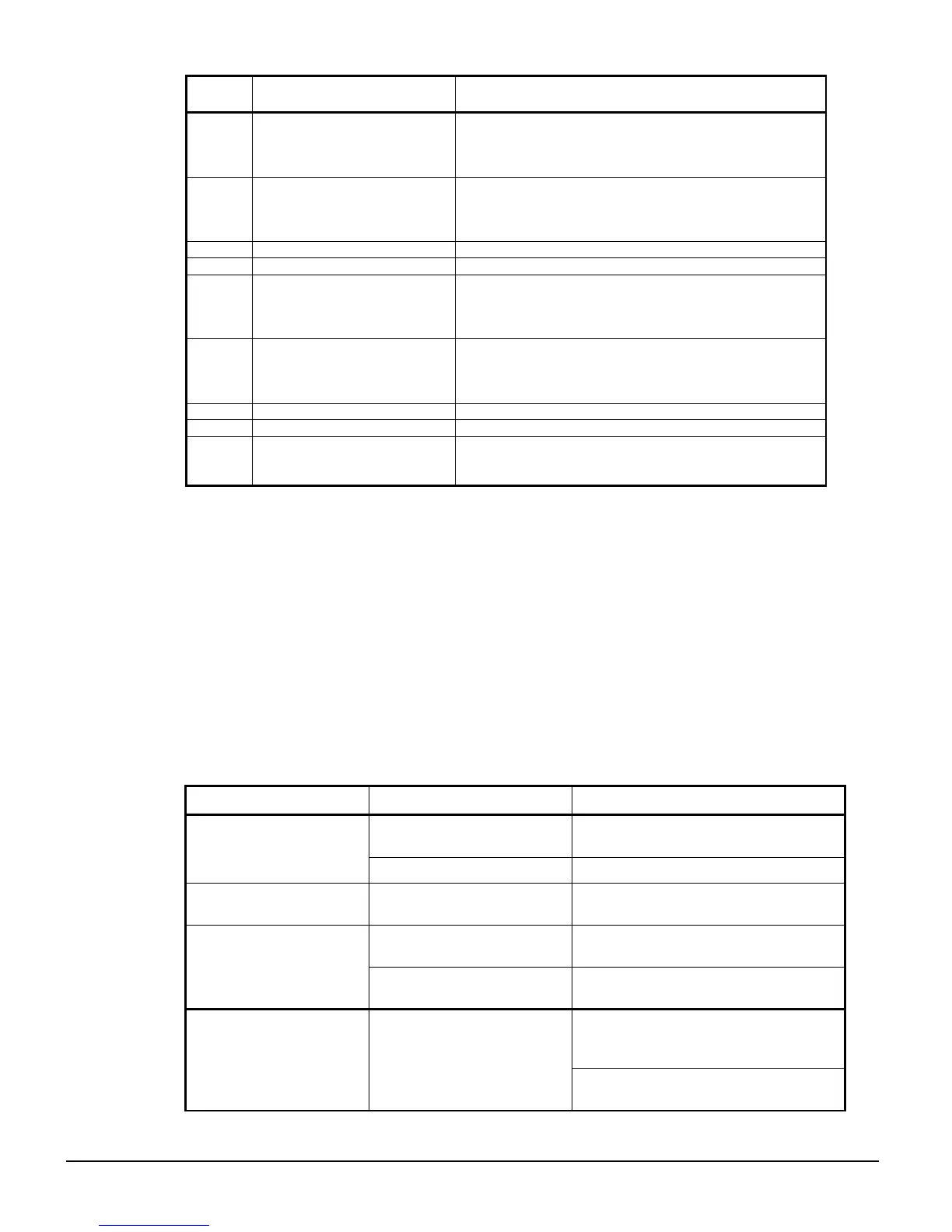
Alarm
Code
Description Notes
A31 Overcurrent
This alarm exists while the D3 is running and the
average current is above the defined threshold, but the
delay for the fault has not yet expired. When the delay
expires, a Fault 31 will occur.
A34 Undercurrent
This alarm exists while the D3 is running and the
average current is below the defined threshold, but the
delay for the fault has not yet expired. When the delay
expires, a Fault 34 will occur.
A35 Reserved
A36 Reserved
A37 Current Imbalance
This alarm exists while the D3 is running and a current
imbalance above the defined threshold is detected, but
the delay for the fault has not yet expired. When the
delay expires, a Fault 37 will occur.
A38 Ground Fault
This alarm exists while the D3 is running and a ground
current above the defined threshold is detected, but the
delay for the fault has not yet expired. When the delay
expires, a Fault 38 will occur.
A47 Stack Overload Alarm This occurs when the stack thermal rises above 105%.
A53 Reserved
A71 Analog Input #1 Trip
This alarm will exist if analog input #1 exceeds the
defined threshold, but the delay for the fault has not yet
expired. When the delay expires, a Fault 71 will occur.
Analog Output Function (P28)
The starter board has a designated terminal connection that will transmit one datum from the
following table via a 0-10VAC signal. The datum point is selected in parameter P28.
0: OFF (no output)
1: Ave Current (0 – 200% RLA)
2: Ave Current (0 – 800% RLA)
3: Ave Voltage (0 – 750VAC)
4: Thermal Overload%
5: KW (0 - 10KW)
6: KW (0 – 100KW)
7: KW (0 – 1MW)
8: KW (0 – 10MW)
9: Analog Input
10: Reserved
11: Calibrate (full 100% output)
Troubleshooting
Table 33, Motor does not start, no output to motor
Condition Cause Solution
Control voltage absent.
Check for proper control voltage input.
Verify fuses and wiring.
Display Blank, CPU
Heartbeat LED on D3
board not blinking.
D3 control board problem. Consult factory.
Fault Displayed. Fault Occurred.
See fault code troubleshooting table for
more details.
Start/Stop control input
problems.
Verify that the start/stop wiring and start
input voltage levels are correct.
Start command given but
nothing happens.
Control Source parameters (
P4-5) not set correctly.
Verify that the parameters are set
correctly.
Check input supply for inline contactor,
open disconnects, open fuses, open
circuit breakers, or disconnected wiring.
NOL or No Line is
displayed and a sratr
command is given, it will
fault in F28.
No line voltage has been
detected
See fault code troubleshooting table for
more details.