8 OM Centrif Micro ΙΙ-5
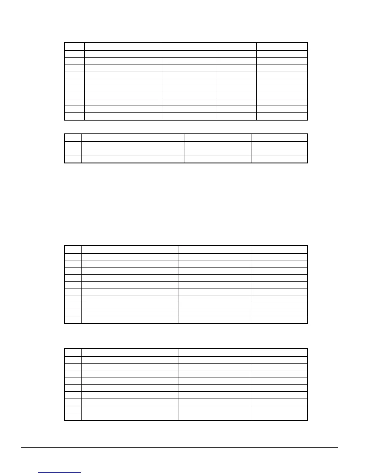
Table 3, Unit Controller, Digital Outputs
# Description Load Output OFF Output ON
NO1
Primary Evaporator Water Pump Pump Contactor Pump OFF Pump ON
NO2
Standby Evaporator Water Pump
Pump Contactor Pump OFF Pump ON
NO3
Primary Condenser Water Pump Pump Contactor Pump OFF Pump ON
NO4
Standby Condenser Water Pump Pump Contactor Pump OFF Pump ON
NO5
Tower Fan #1 Fan Contactor Fan OFF Fan ON
NO6
Tower Fan #2 Fan Contactor Fan OFF Fan ON
NO7
(unused)
NO8
Alarm Alarm Indicator Alarm OFF Alarm ON
NO9
Tower Fan #3 Fan Contactor Fan OFF Fan ON
NO10
Tower Fan #4 Fan Contactor Fan OFF Fan ON
Table 4, Unit Controller, Analog Outputs
# Description Output Signal Range
Y1
Cooling Tower Bypass Valve Position 0 to 10 VDC 0 to 100% Open
Y2
Cooling Tower VFD Speed 0 to 10 VDC 0 to 100%
Y3
Electronic Expansion Valve (EEV) 0 to 10 VDC 0 to 100% Open
Compressor Controller
The compressor controller's primary function is controlling and protecting the compressor. No
setpoint inputs are made with it. There is one compressor controller for each compressor on a dual
chiller unit. The compressor controller receives, processes, and sends data to other controllers and
devices and to the compressor starter or variable frequency drive (VFD). With some operator
intervention the compressor controller can operate the compressor(s) if the unit controller and/or
the operator interface touch screen are unavailable. Inputs and outputs are as follows:
Table 5, Compressor Controller, Analog Inputs
# Description Signal Source Range
B1
Oil Sump Pressure 0.5 to 4.5 VDC 0 to 150 psi
B2
Oil Supply Pressure to Compressor 0.5 to 4.5 VDC 0 to 450 psi
B3
Evaporator Refrigerant Pressure 0.1 to 0.9 VDC 0 to 150 psi
B4
Oil Sump Temperature NTC Thermister (10k@25°C) -58 to 212°F
B5
Compressor Suction Temperature NTC Thermister (10k@25°C) -58 to 212°F
B6
Condenser Refrigerant Pressure 0.5 to 4.5 VDC 0 to 450 psi
B7
Compressor Discharge Temperature NTC Thermister (10k@25°C) -58 to 212°F
B8
Motor Current 0.5 to 4.5 VDC 0 to 125% RLA
B9
Oil Feed Temperature NTC Thermister (10k@25°C) -58 to 212°F
B10
Leaving Evaporator Water Temperature NTC Thermister (10k@25°C) -58 to 212°F
Table 6, Compressor Controller, Digital Inputs
# Description Signal Signal
ID1
Manual Off 0 VAC (Off) 24 VAC (Auto)
ID2
Mech High Pressure 0 VAC (High Pressure ) 24 VAC (OK)
ID3
Motor High Temperature 0 VAC (High Temp) 24 VAC (OK)
ID4
Vanes Closed Switch 0 VAC (Not Closed) 24 VAC (Closed)
ID5
Starter Transition 0 VAC (No Transition) 24 VAC (Transition)
ID6
Starter Fault 0 VAC (Fault) 24 VAC (No Fault)
ID7
Evap Flow 0 VAC (N0 Flow) 24 VAC (Flow)
ID8
Cond Flow 0 VAC (N0 Flow) 24 VAC (Flow)
ID9
Vanes Open Switch 0 VAC (Not Open) 24 VAC (Open)