OM Centrif Micro ΙΙ-5 7
Software
The same model controller is used as either a unit controller or a compressor controller. The
controller operation is determined by the setting of the controller pLAN address. These settings
are all made in the factory during unit testing. Settings are different with multiple chillers and will
be set by the startup technician.
The operating software is revised occasionally. The version residing in a given control is
identified on the screen at boot-up or can be viewed at any time by pressing the Right and Up
Arrows simultaneously. It is also displayed on the OITS SERVICE screen.
Unit Controller
There is one unit controller mounted on the chiller that serves both compressor units.
Unit and compressor on/off switches are mounted in the unit controller panel located adjacent to
the OITS panel. They are designated 1 for on and O for off. The compressor on/off switch should
only be used when an immediate stop is required since the normal shut down sequence is
bypassed.
The switch panel also has a circuit breaker that interrupts power to the cooling tower fans, valves
and evaporator and condenser pumps, if any of these are tied into the MicroTech II for control of
their operation. If these components operate independently from the chiller control, the breaker
has no effect.
There is an emergency shutdown switch located on the left outside of the panel that causes an
immediate shutdown of both compressors.
The unit controller's primary function is processing data relating to the entire chiller unit
operation, as compared to data relating to the compressor operation. The unit controller processes
information and sends data to other controllers and devices and relays information to the OITS for
graphic display. It has a 4x20 LCD display and keys for accessing data and changing setpoints.
The LCD can display most of the same information as the OITS and can operate the chiller
independently if the OITS is not available. Inputs and outputs are shown in the following tables.
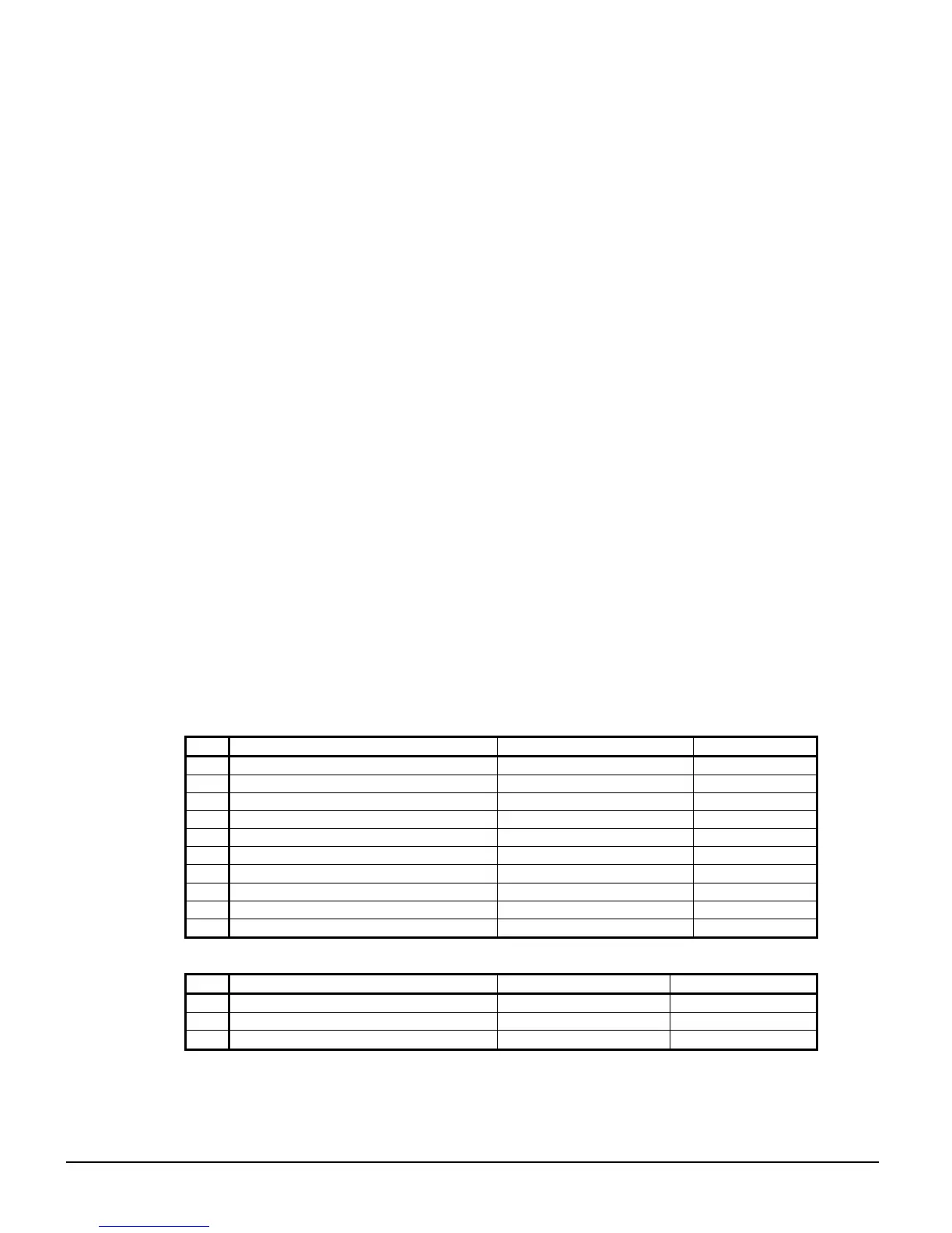
Table 1, Unit Controller, Analog Inputs
# Description Signal Source Range
B1
Reset of Leaving Water Temperature 4-20 mA Current 0-(10 to 80°F)
B2
Entering Evaporator Water Temperature NTC Thermister (10k@25°C) -58 to 212°F
B3
Entering Condenser Water Temperature NTC Thermister (10k@25°C) -58 to 212°F
B4
Leaving Condenser Water Temperature NTC Thermister (10k@25°C) -58 to 212°F
B5
Liquid Line Refrigerant Temperature NTC Thermister (10k@25°C) -58 to 212°F
B6
Demand Limit 4-20 mA Current 0-100 %RLA
B7
Evaporator Water Flow 4 to 20 mA Current 0 to 10,000 gpm
B8
Condenser Water Flow 4 to 20 mA Current 0 to 10,000 gpm
B9
Entering Heat Recovery Temp. NTC Thermister (10k@25°C) -58 to 212°F
B10
Leaving Heat Recovery Temperature NTC Thermister (10k@25°C) -58 to 212°F
Table 2, Unit Controller, Digital Inputs
# Description Signal Signal
ID1
Unit OFF Switch 0 VAC (Stop) 24 VAC (Auto)
ID2
Remote Start/Stop 0 VAC (Stop) 24 VAC (Start)
ID3
Mode Switch 0 VAC (Cool) 24 VAC (Ice or Heat)