26 OM Centrif Micro ΙΙ-5
STARTER SETPOINTS
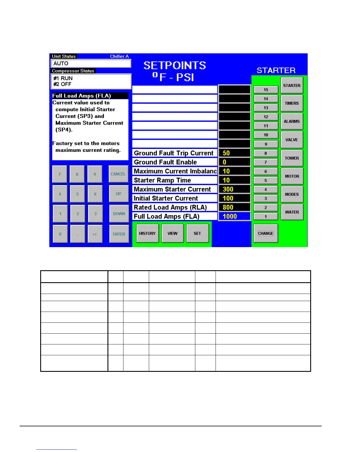
Figure 14, Optional Starter Setpoint Screen
Table 12, Starter Setpoints
Description No. Default Range
Pass-
word
Comments
Ground Fault Current Trip 8 1 % 1 to 100% RLA M
Sets the value for ground current above
which the compressor will be shut down
Ground Fault Enable 7 OFF On or OFF M Turns the ground fault option on or off
Maximum Current Unbalance 6 10% 5% to 40% T
Sets the value for current unbalance above
which the compressor will be shut down
Starter Ramp Time 5 15 sec. 0 to 30 seconds T
Sets the time the starter ramps up the
motor current
Maximum Starter Current 4 600%
100% to 800%
of FLA (SP1)
T
Sets the maximum current when the
compressor starts
Initial Starter Current 3 100%
50% to 400% of
FLA (SP1)
T
Sets the initial current when the
compressor starts
Rated load Amps 2 1 A
Factory set at
design conditions
T
Value that gives the 100% RLA value and
used for motor protection
Full Load Amps 1 1 A
Factory set to
motor max current
rating
T Value used to compute SP3 and SP4
The setpoints shown above are for solid state starters. Other types of starters will have slightly different
setpoints. Units without the starter display option will have their setpoints set in the starter itself.