OM Centrif Micro ΙΙ-5 35
MODES Setpoints
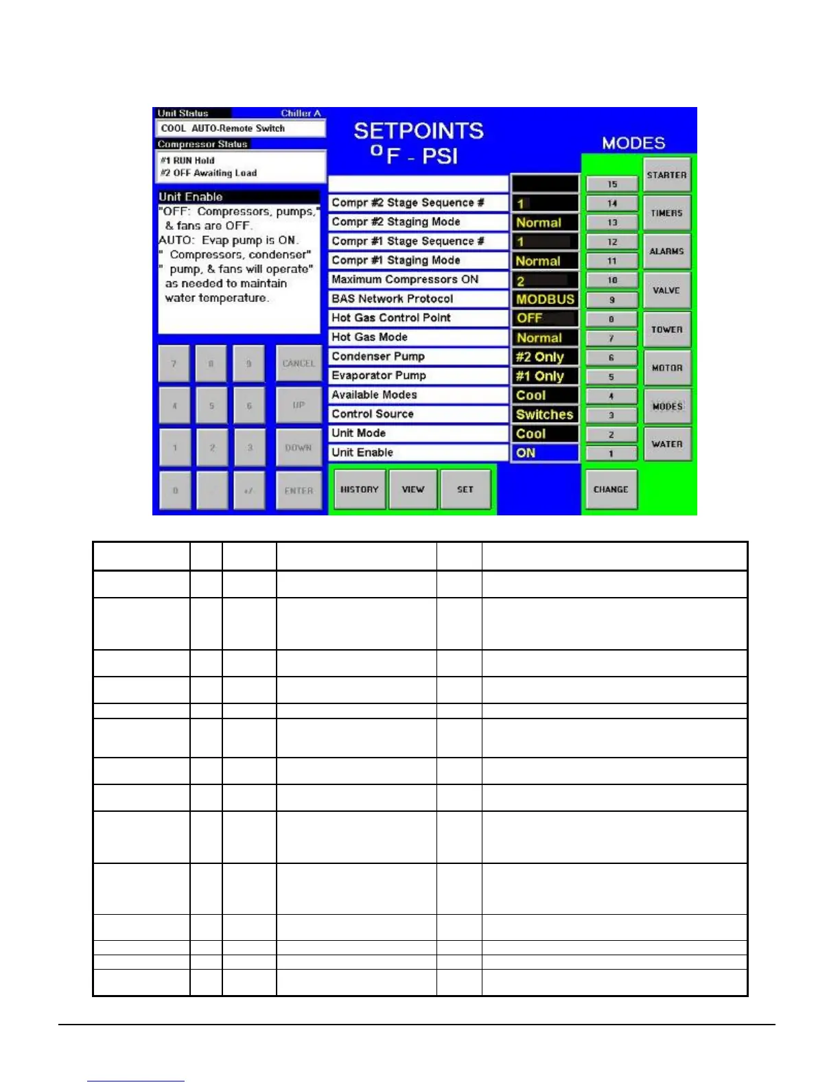
Figure 20, MODES Setpoint Screen
Table 18, MODE Setpoint Settings
Description No. Default Range
Pass-
word
Comments
Comp # 2 Stage
Sequence
14 1 1,2, … (# of Compressors) M
Sets sequence number for # 2 compressor, if 1 it is
always first to start, if 2 is always second (Note 1)
Comp # 2 Mode 13 Normal
Normal, Efficiency, Pump,
Standby
M
Normal uses standard sequencing
Efficiency starts one compressor on each dual unit
Pump starts all compressors on one chiller first
Standby uses this compressor only if another fails.
Comp #1 Stage
Sequence
12 1 1,2, … (# of Compressors) M
Sets sequence number for # 1 compressor, if 1 it is
always first to start, if 2 is always second (Note 1)
Comp #1 Mode 11 Normal
Normal, Efficiency, Pump,
Standby
M Ditto No. 12.
Max. Comp. ON 10 1 1-16 M Total number of compressors minus standby
BAS Protocol 9 Modbus
None, Local, Remote,
BACnet, LonWorks,
MODBUS,
M
Sets BAS Standard Protocol to be used or LOCAL
if none.
Hot Gas Control
Point
8 30% 20 to 70% T LWT or % RLA below which HGBP solenoid is on
Hot Gas Bypass
Mode
7 Normal Off, Water LWT, %RLA T Sets mode for hot gas operaton
Cond Pump 6
Pump
#1 Only
Pump #1 Only, Pump #2
Only, Auto Lead, #1 Primary,
#2 Primary
M
Pump #1 Only, Pump #2 Only, use only these
pumps
AUTO, balance hours between #1 and #2
#1 Primary, #2 Primary, if primary fails, use other
Evap Pump 5
Pump
#1 Only
Pump #1 Only, Pump #2
Only, Auto Lead, #1 Primary,
#2 Primary
M
Pump #1 Only, Pump #2 Only, use only these
pumps
AUTO, balance hours between #1 and #2
#1 Primary, #2 Primary, if primary fails, use other
Available Modes 4 COOL
COOL, COOL/ICE, ICE,
COOL/HEAT, HEAT
T Sets modes that can be selected in SP 2
Control Source 3 LOCAL LOCAL, BAS, SWITCH O Sets control source
Unit Mode 2 COOL COOL, ICE, HEAT, TEST Selects from MODES in SP4
Unit Enable 1 OFF OFF, ON O
OFF, everything is off. ON, Evap pump on, comp,
cond pump and tower on as required to meet LWT