OM Centrif Micro ΙΙ-5 33
NOTE: Setpoints 14 and 15 are site specific dealing with system fluid mass, component
size and other factors affecting the reaction of the system to control inputs. These
setpoints should be set by personnel experienced with setting up this type of control.
c) If LIFT was selected for fan control, use
i) SP3, Set the VALVE TARGET (setpoint), usually 30 psi below the minimum fan
stage setpoint established in TOWER SP12. This keeps full flow through the tower
until the last fan is staged off.
ii) SP5, Set VALVE DEADBAND, the default of 6 psi is a good place to start.
iii) SP8, Set MINIMUM VALVE POSITION when EWT is at or below SP9. Default is
0%.
iv) SP9, Set the EWT at which the valve position will be at (SP8). Default is 60°F.
v) SP12, Set the minimum position to which the valve can go. Default is 10%.
vi) SP13, Set the maximum position to which the valve can go. Default is 100%.
vii) SP14, Set the control gain for error. Default is 25.
viii) SP15, Set the control gain for slope. Default is 25.
NOTE: Setpoints 14 and 15 are site specific dealing with system fluid mass, component
size and other factors affecting the reaction of the system to control inputs. These
setpoints should be set by personnel experienced with setting up this type of control.
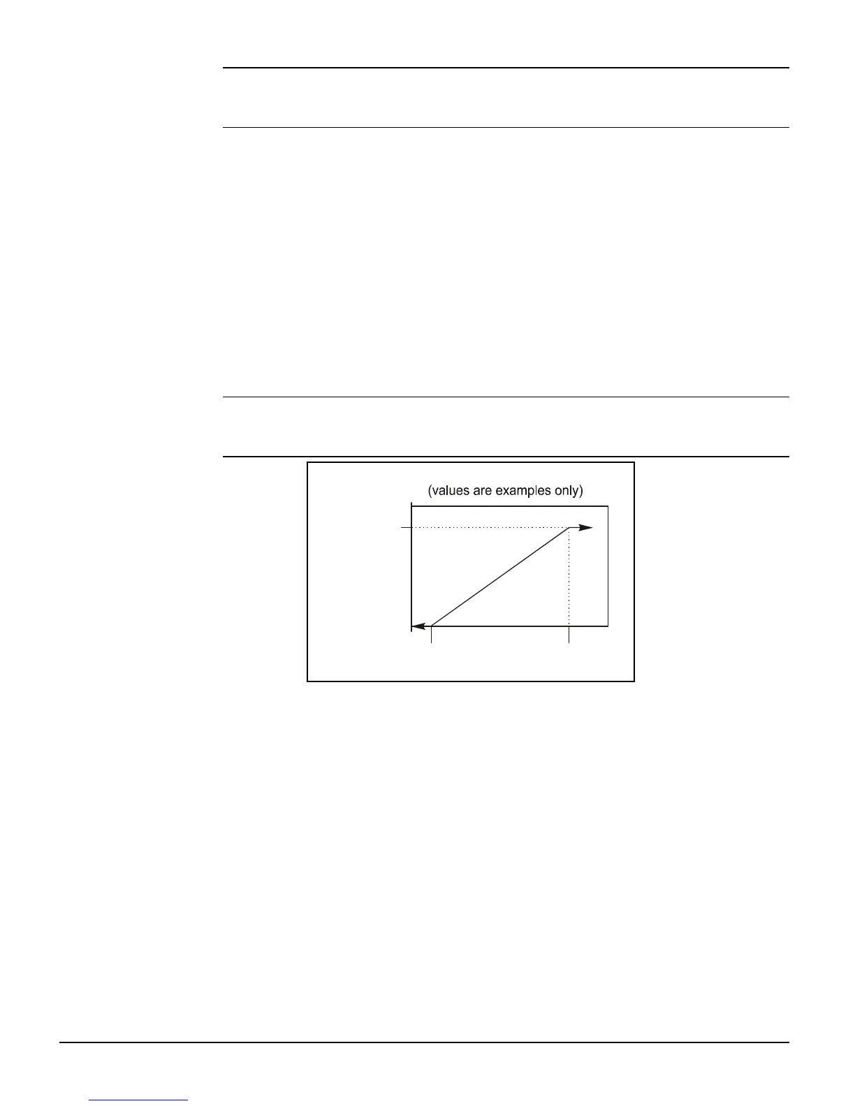
Initial Valve Position
Set Point (90%)
Min Start Position
Set Point (10%)
Max Position
@ Setpoint
(90°F)
Min Position
@ Setpoint
(60°F)
See Figure 2 on page 11 for fan staging and bypass valve field wiring connection points.
Tower Staging with Bypass Valve Controlled by Fan Stage (VALVE STAGE)
This mode is similar to #2 above except that the bypass valve setpoint changes to be set at the
same point of whatever fan stage is active rather than just maintaining a single minimum
condenser EWT. In this mode the valve controls between fan stages and tries to maintain the
fan stage setting in effect. When it is max open or max closed (staging up or down) and the
temperature (or lift) moves to the next fan stage, the valve will go the opposite max setting.
This mode reduces fan cycling.
This mode is programmed the same as Mode #2 above except that in SETPOINT, TOWER,
SP2, VALVE STAGE is selected instead of VALVE SP.
Fan VFD, No Bypass Valve (VFD STAGE)
The fan VFD mode assumes the tower is driven by one large fan. Set up is as above except in
SETPOINT, TOWER, SP2, VALVE/VFD is selected.