OM Centrif Micro ΙΙ-5 41
Alarms fall into three distinct categories: Faults, Problems, and Warnings as detailed in the following
section.
Fault Alarms
The following table identifies each fault alarm, its display, gives the condition that causes the alarm to
occur, and states the action taken because of the alarm. All fault alarms require a manual reset and trigger
the remote alarm signal.
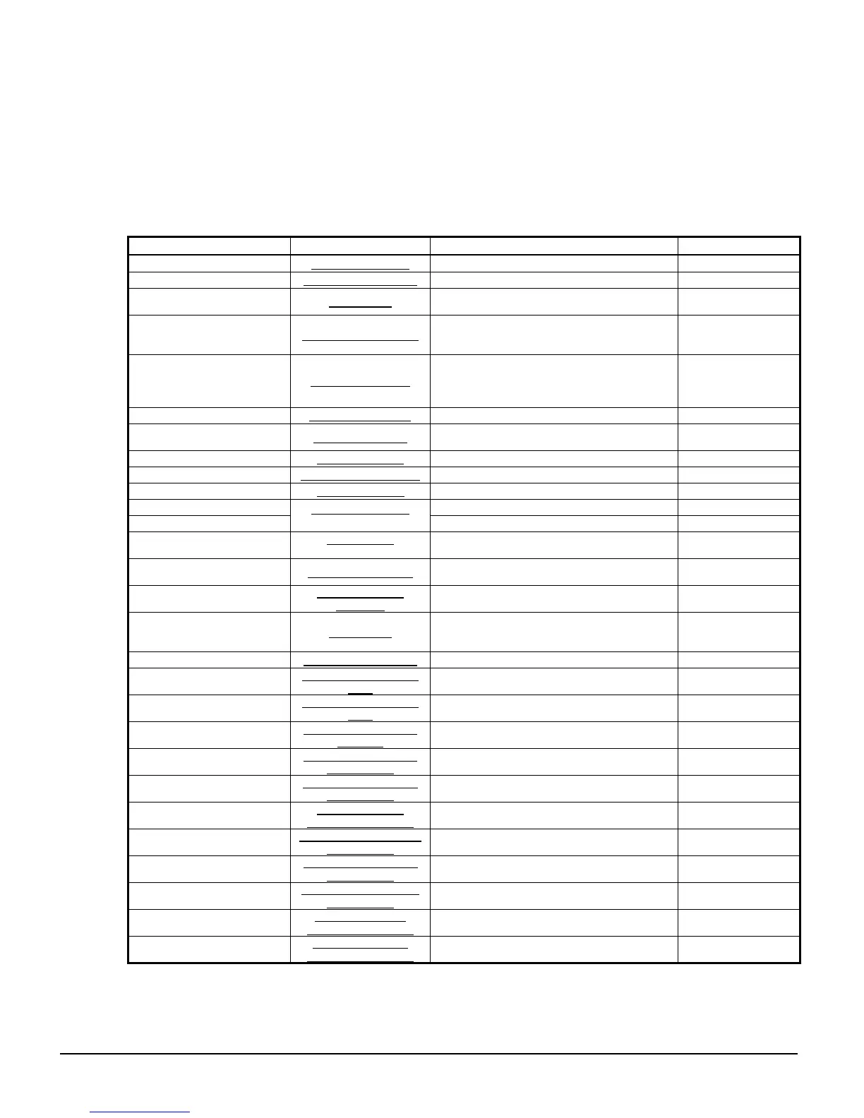
Table 20, Fault Alarm Description
Description Display Occurs When: Action Taken
Low Evaporator Pressure Evap Pressure Low Evaporator Press < Low Evap Pressure SP Rapid Stop
High Condenser Pressure Condenser Press High Cond Press > High Condenser Pressure SP Rapid Stop
Vanes Open No Start Vanes Open
Compressor state = PRELUBE for 30 sec
after Prelube timer expires
Rapid Stop
Low Oil Delta Pressure Oil Delta Pressure Low
(Comp State=PRELUBE, RUN, UNLOAD, or
POSTLUBE)
& Net Oil Press < Low Net Oil Press SP
Rapid Stop
Low Oil Feed Temperature Oil Feed Temp Low
(Comp State=RUN or UNLOAD) &
Oil Feed temp <
(Evap Saturated Refr Temp + Low Oil Delta
Temperature SP) for > 1 min
Rapid Stop
High Oil Feed Temperature Oil Feed Temp High Temp > High Oil Feed Temperature SP Rapid Stop
Low Motor Current Motor Current Low
I < Motor Current Threshold with Compressor
ON for 30 sec
Rapid Stop
High Discharge Temperature Disch Temp High Temp > High Discharge Temperature SP Rapid Stop
Mechanical High Pressure Mechanical High Press Digital Input = High Pressure Rapid Stop
High Motor Temperature High Motor Temp Digital Input = High Temperature Rapid Stop
Surge Temp High Surge Temp > Surge Temp SP Rapid Stop
Surge Temp Slope High
Surge Temperature
Note 1
Surge Temp Slope > Surge High Slope SP Rapid Stop
Compressor Surge Eminent
Surge Switch
Note 2
Delta-P Switch Senses Reverse Pressure
Across the Discharge Check Valve
Rapid Stop
No Starter Transition No Starter Transition
Starter Transition Digital Input = No Transition
AND Compressor ON for > 15 seconds
Rapid Stop
No Compressor Stop
Current High with
Comp Off
%RLA > Motor Current Threshold SP with
Compressor OFF for 30 sec
Annunciation
Starter Fault Starter Fault
Starter Fault Digital Input = Fault AND
Compressor State = START, PRELUBE,
RUN, or UNLOAD
Rapid Stop
Low Oil Pressure Start Oil Pressure Low-Start Compressor State = START for 30 sec Rapid Stop
No Evaporator Water Flow
Evaporator Water Flow
Loss
Chilled Water Flow Switch Open Rapid Stop
No Condenser Water Flow
Condenser Water Flow
Loss
Condenser Water Flow Switch Open Rapid Stop
Leaving Evaporator Water
Temperature Sensor Fault
Evap LWT Sensor Out
of Range
Sensor shorted or open Rapid Stop
Evaporator Pressure Sensor
Fault
Evap Pressure Sensor
Out of Range
Sensor shorted or open Rapid Stop
Condenser Pressure Sensor
Fault
Cond Pressure Sensor
Out of Range
Sensor shorted or open Rapid Stop
Suction Temperature Sensor
Fault
Suction Pressure
Sensor Out of Range
Sensor shorted or open Rapid Stop
Discharge Temperature
Sensor Fault
Discharge Temp Sensor
Out of Range
Sensor shorted or open Rapid Stop
Oil Feed Temperature
Sensor Fault
Oil Feed Temp Sensor
Out of Range
Sensor shorted or open Rapid Stop
Oil Sump Temperature
Sensor Fault
Oil Sump Temp Sensor
Out of Range
Sensor shorted or open Rapid Stop
Oil Feed Pressure Sensor
Fault
Oil Feed Pressure
Sensor Out of Range
Sensor shorted or open Rapid Stop
Oil Sump Pressure Sensor
Fault
Oil Sump Pressure
Sensor Out of Range
Sensor shorted or open Rapid Stop
NOTES:
1.
Surge Temperature is defined as the suction temperature minus the leaving chilled water temperature.
2.
Delta-P switch used only on chillers manufactured in Europe.
3.
Starter alarm faults will be sent from the starter and will also appear here. They are discussed elsewhere in this manual.