IM-447 / Page 17
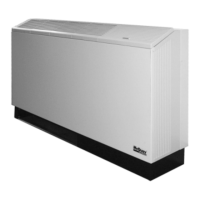
60 Hertz
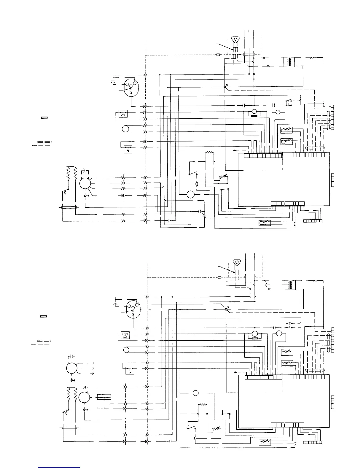
50 Hertz
BK10
(Not Req’d on
all sizes)
HP
M1
CAP
R
C
S
BK11
T4
WH1
BR
BK12
BR
RV
BK2
RD(013)
OR(016)
CAP
GN/YE
6
5
1
6
PCB
Microtech
Controller
10
13
11
12
15
14
5
10
8
25
26
30
31
33
7
9
8
10
16
Ribbed
Lead
Field
Connections
G N L1
GN/YE
BK
RD 208/230V
WH 115/265V
TB3-1
TB3-4
12
BK
OR 230V
RD 208V
YE
BL
36
YE
51
37
9
11
R1
R4
SW2
BK
RD
2
42
4
5
2
1
7
1
3
3
R1
R4
S5
S2
24
25
26
27
29
31
33 35
30
32
34
36
56
55
54
53
YE
WH
RD
GN
BL
OR
BK
51
52
Auxiliary Module
(Optional)
1
2
1
2
3
4
5
6
7
Spare Relay Com
62
63
64
65
66
67
68
TB1
70
69
6
9
SW1
CS
B
A
BR1
WH2
WH3
15 POS AMP
17
HTR
GN/YE
OH1
WH
BL3
4
2
1
6 POS AMP
SIDE PANEL
RD1
BR2
BK1
BL2
OR2
BL1
OR1
3
9
4
4
5
R12
R12
2
1
7
73
E
L
U
P
C
TB2
Lon Talk
Lon Talk
12
11
10
9
8
7
6
5
4
3
2
1
Remote DI Src
Remote DI Sig
Spare Relay No
Spare Relay NC
Rm Sensor LED
Tenant Override
Rm Sensor In
Rm Sensor Com
24V AC Com
J1
J2
J4
J5
J6
37
Condensate
Lo Temp Src
Lo Temp Sig
Lo Press Sig
Hi Press Sig
RV Com
RV Out
Comp Com
Fan Com
Fan Out
24V AC
Lo Press Src
24V Gnd
Comp Out
Discharge Air
Com
Discharge Air In
Water Out Com
Water Out In
Aux Module OC +
Aux Module Sel 2
Aux Module Sel 1
Aux Module Clk
Aux Module Rcv
Aux Module Xmt
Aux Module
OC Com
3
4
5
6
7
8
9
10
11
12
13
14
2
1
3
4
5
6
7
8
9
10
11
2
1
J1
Red
Tape
End
4
GND
OR3
GN/YE
CRD
J2
12345
67
13
S1
73
YE
62
BK BL
TB4
RES2
13
BK
POT1
SW3
6
1
GN/YE
8
BL1
80
79
Transformer
GN/YE
BR
BR
BK3
17
16
2
BL3
OR3
RD
BK
BK
BR
BR
Resistor
BK1
(008-
010)
BK1
(004-
006)
Fan
Motor
(Size
004 -
010)
Fan
Motor
(Size
013 -
016)
GN/YE
CAP
BR
BR
WH
BL(013)
BK(016)
5
4
6
BK10
(Not Req’d on
all sizes)
HP
M1
CAP
R
C
S
BK11
T4
WH1
BR
BK12
BR
RV
BK2
CAP
GN/YE
6
5
6
PCB
Microtech
Controller
10
13
11
12
15
14
5
10
8
25
26
30
31
33
7
9
8
10
16
Ribbed
Lead
Field
Connections
G N L1
GN/YE
BK
RD 208/230V
WH 115/265V
TB3-1
TB3-4
12
BK
WH 115V
RD 208V
OR 230V
BR 265V
YE
BL
36
YE
51
37
9
11
R1
R4
SW2
BK
RD
24
2
4
5
2
1
7
1
3
3
R1
R4
S5
S2
24
25
26
27
29
31
33
35
30
32
34
36
56
55
54
53
YE
WH
RD
GN
BL
OR
BK
51
52
Auxiliary Module
(Optional)
1
2
1
2
3
4
5
6
7
Spare Relay Com
62
63
64
65
66
67
68
TB1
73
6
9
SW1
CS
BR1
WH2
WH3
15 POS AMP
17
HTR
GN/YE
OH1
WH
BL3
4
2
1
6 POS AMP
SIDE PANEL
RD1
BR2
BK1
BL2
OR2
BL1
OR1
3
9
4
4
5
R12
R12
2
1
7
73
E
L
U
P
C
TB2
Lon Talk
Lon Talk
12
11
10
9
8
7
6
5
4
3
2
1
Remote DI Src
Remote DI Sig
Spare Relay No
Spare Relay NC
Rm Sensor LED
Tenant Override
Rm Sensor In
Rm Sensor Com
24V AC Com
J1
J2
J4
J5
J6
37
Condensate
Lo Temp Src
Lo Temp Sig
Lo Press Sig
Hi Press Sig
RV Com
RV Out
Comp Com
Fan Com
Fan Out
24V AC
Lo Press Src
24V Gnd
Comp Out
Discharge Air
Com
Discharge Air In
Water Out Com
Water Out In
Aux Module OC +
Aux Module Sel 2
Aux Module Sel 1
Aux Module Clk
Aux Module Rcv
Aux Module Xmt
Aux Module
OC Com
3
4
5
6
7
8
9
10
11
12
13
14
2
1
3
4
5
6
7
8
9
10
11
2
1
J1
Red
Tape
End
20
GND
OR3
CRD
J2
12345
67
13
S1
YE
BK
BK
TB4
RES2
13
6
1
GN/YE
8
BL1
80
79
BR
BR
BK3
17
16
2
BL3
OR3
RD(007-015)
OR(019)
BR BR
69
70
SW3
62
POT1
BL
BA
R12
20
4
1
4
21
(007,
(015)
21
(007,
015)
X1
1
3
7
BL6
(009,012,019)
21
(009,
012,
019)
BL(007,015)
BK(009,012,019)
BL(009,012,019)
M
Legend
Symbol Description Setpoint
CAPCapacitor
CRD Cordset (OPT)
CS Condensate Sensor
HP Switch - High Pressure
HTRHeater - Electric
MMotor - Fan
M1 Motor - Compressor
PCSController - MicroTech
PO11 Potentiometer - Tenant Set Point
R1 Relay Compressor
R4 Relay - Fan
R12 Relay - Electric Heat
RES2 Resistor - Tenant Set Point
RV Reversing Valve
S1 Sensor - Return Air
S2 Sensor - Discharge Air
S5 Sensor - Water Out
SW1 Switch - Start/Stop
SW2 Switch - Hi/Low Fan Speed
SW3 Switch - Tenant Override
T4 Thermostat - Low Limit 38˚ F
TB1 Terminal Block - Communications
TB2 Terminal Block - Remote Signal
TB3 Terminal Block - Line Voltage
TB4 Terminal Block - Low Voltage
X1 Transformer
Transorb
>> Plug Connection
TB Terminal Block
ACO Automatic Change Over
MCO Manual Change Over
BR Boilerless Relay
HR Heater Relay
Shielded Cable
Optional Wiring
Legend
Symbol Description Setpoint
CAPCapacitor
CRD Cordset (OPT)
CS Condensate Sensor
HP Switch - High Pressure
HTRHeater - Electric
MMotor - Fan
M1 Motor - Compressor
PCSController - MicroTech
PO11 Potentiometer - Tenant Set Point
R1 Relay Compressor
R4 Relay - Fan
R12 Relay - Electric Heat
RES2 Resistor - Tenant Set Point
RV Reversing Valve
S1 Sensor - Return Air
S2 Sensor - Discharge Air
S5 Sensor - Water Out
SW1 Switch - Start/Stop
SW2 Switch - Hi/Low Fan Speed
SW3 Switch - Tennant Override
T4 Thermostat - Low Limit 38˚ F
TB1 Terminal Block - Communications
TB2 Terminal Block - Remote Signal
TB3 Terminal Block - Line Voltage
TB4 Terminal Block - Low Voltage
X1 Transformer
Transorb
>> Plug Connection
TB Terminal Block
ACO Automatic Change Over
MCO Manual Change Over
BR Boilerless Relay
HR Heater Relay
Shielded Cable
Optional Wiring
 Loading...