USB-1208LS User's Guide Functional Details
External components
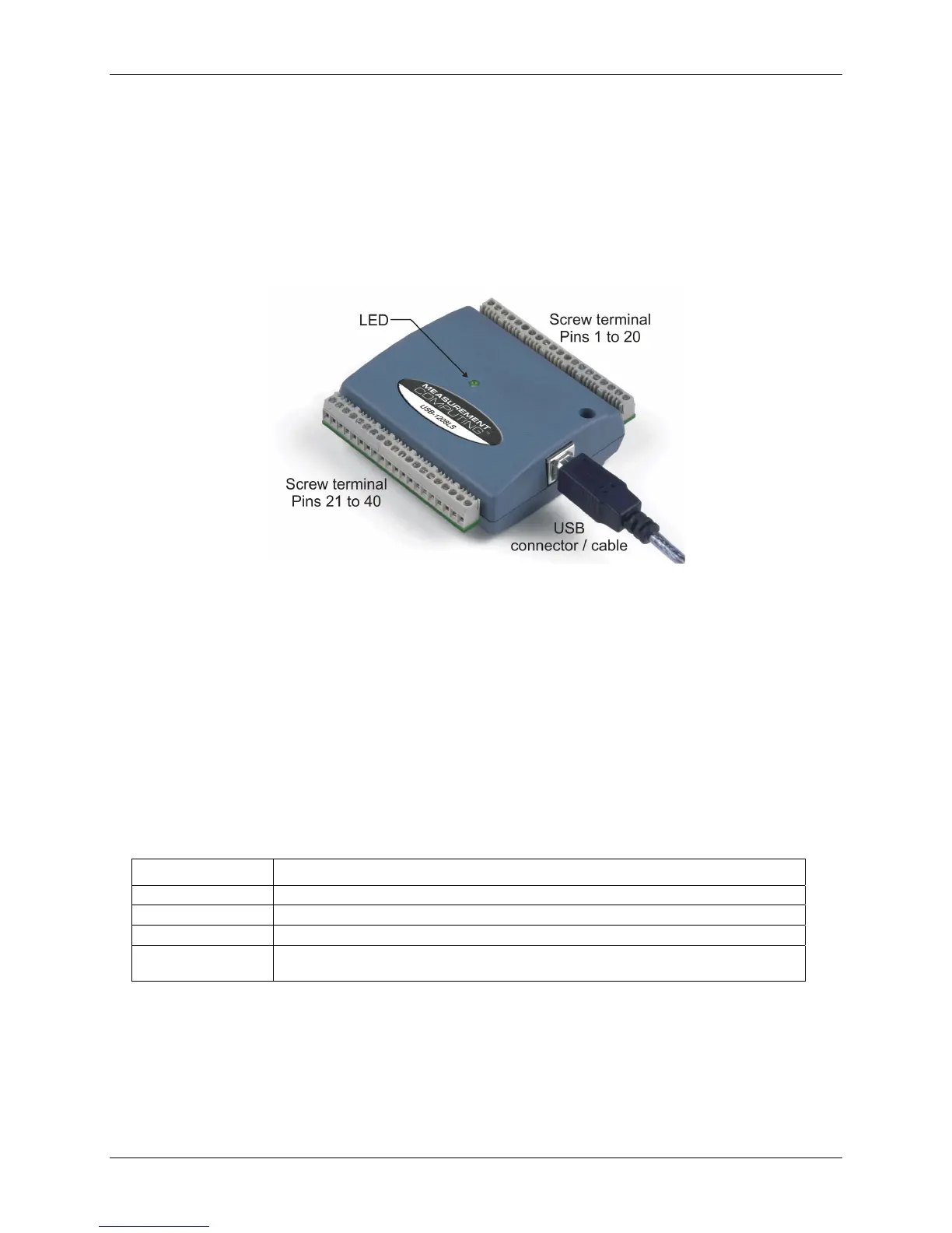
The USB-1208LS has the following external components, as shown in
Figure 3-1.
! USB connector
! LED
! Screw terminal banks (2)
Figure 3-1. USB-1208LS external components
USB connector
The USB connector is on the right side of the USB-1208LS housing. This connector provides +5V power and
communication. The voltage supplied through the USB connector is system-dependent, and may be less than
5V. No external power supply is required.
LED
The LED on the front of the housing indicates the communication status of the USB-1208LS. It uses up to 5
mA of current and cannot be disabled. defines the function of the USB-1208LS LED. Table 3-1
Table 3-1. LED illumination
When the LED is… It indicates…
Steady green The USB-1208LS is connected to a computer or external USB hub.
Blinks continuously Data is being transferred.
Blinks three times Initial communication is established between the USB-1208LS and the computer.
Blinks at a slow rate
The analog input is configured for external trigger. The LED stops blinking and illuminates
steady green when the trigger is received.
3-2