USB-1208LS User's Guide Functional Details
Screw terminal wiring
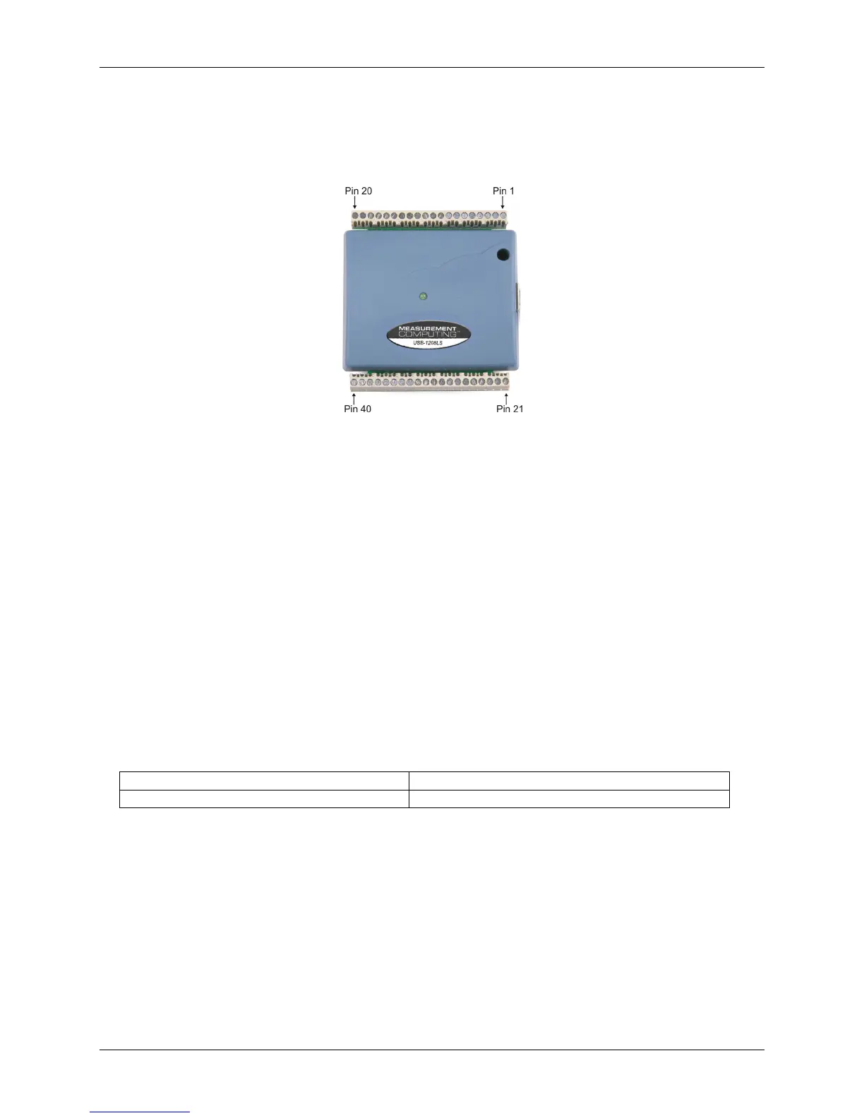
The USB-1208LS has two rows of screw terminals—one row on the top edge of the housing, and one row on
the bottom edge. Each row has 20 connections. Pin numbers are identified in Fi . gure 3-2
Figure 3-2. USB-1208LS Screw terminal pin numbers
Screw terminal – pins 1-20
The screw terminals on the top edge of the USB-1208LS (pins 1 to 20) provide the following connections:
! Eight analog input connections (
CH0 IN to CH7 IN)
! Two analog output connections (D/A OUT 0 to D/A OUT 1)
! One external trigger source (
TRIG_IN)
! One external event counter connection (CTR)
! Seven GND connections (GND)
! One calibration terminal (
CAL)
Screw terminal – pins 21-40
The screw terminals on the bottom edge of the (pins 21 to 40) provide the following connections:
! 16 digital I/O connections (
PortA0 to Port A7, and Port B0 to Port B7)
! One power connection (PC+5 V)
! Three ground connections (GND)
Main connector and pin out
Connector type Screw terminal
Wire gauge range 16 AWG to 30 AWG
3-3