USB-1208LS User's Guide Functional Details
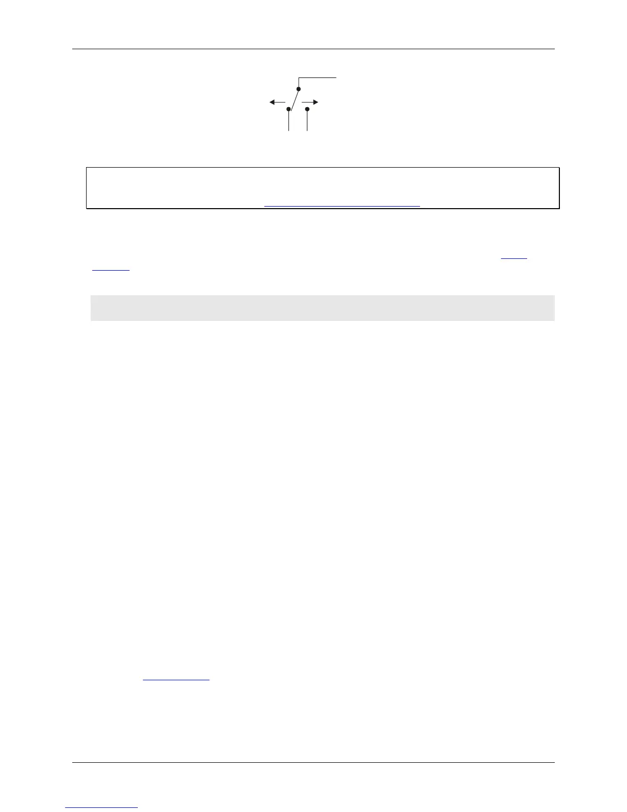
+5V+GND
Port A0
Figure 3-9. Schematic showing switch detection by digital channel Port A0
For more information on digital signal connections
For more information on digital signal connections and digital I/O techniques, refer to the Guide to Signal
Connections (available on our web site at www.mccdaq.com/signals/signals.pdf).
Power terminals
The PC +5 V connection (pin 30) is on the bottom screw terminal of the USB-1208LS. Refer to the pinout
diagrams on page 3-4 for the location of this pin. This terminal draws power from the USB connector. The +5 V
screw terminal is a 5 volt output that is supplied by the host computer.
Caution! The +5V terminal is an output. Do not connect to an external power supply or you may damage
the USB-1208LS and possibly the computer.
The maximum total output current that can be drawn from all USB-1208LS connections (power, analog and
digital outputs) is 500 mA. This maximum applies to most personal computers and self-powered USB hubs.
Bus-powered hubs and notebook computers may limit the maximum available output current to 100 mA.
Just connecting the USB-1208LS to your computer draws 20 mA of current from the USB +5 V supply. Once
you start running applications with the USB-1208LS, each DIO bit can draw up to 2.5 mA, and each analog
output can draw 30 mA. The maximum amount of +5 V current available for experimental use, over and above
that required by the USB-1208LS, is the difference between the total current requirement of the USB device
(based on the application), and the allowed current draw of the PC platform (500 mA for desktop PCs and self-
powered hubs, or 100 mA for bus-powered hubs and notebook computers).
With all outputs at their maximum output current, you can calculate the total current requirement of the USB-
1208LS USB +5 V as follows:
(USB-1208LS @ 20 mA) + (16 DIO @ 2.5 mA ea) + (2 AO @ 30 mA ea ) = 120 mA
For an application running on a PC or powered hub, the maximum available excess current is 500 mA−120 mA
= 380 mA. This number is the total maximum available current at the PC+5V screw terminals. Measurement
Computing highly recommends that you figure in a safety factor of 20% below this maximum current loading
for your applications. A conservative, safe user maximum in this case would be in the 300-320 mA range.
Since laptop computers typically allow up to 100 mA, the USB-1208LS in a fully-loaded configuration may be
above that allowed by the computer. In this case, you must determine the per-pin loading in the application to
ensure that the maximum loading criteria is met. The per-pin loading is calculated by simply dividing the +5 V
by the load impedance of the pin in question.
Ground terminals
The 10 ground (GND) connections are identical, and provide a common ground for all USB-1208LS functions.
Refer to the pinout diagrams on page 3-4 for the location of the GND terminal pins.
3-8