USB-1208LS User's Guide Functional Details
Since the analog inputs are restricted to a −10 V to +20 V signal swing with respect to ground, all ranges except
±20V can realize a linear output for any differential signal with zero common mode voltage and full scale signal
inputs. The ±20 V range is the exception. You cannot put −20 V on CHHI and 0 V on CHLO since this violates
the input range criteria.
Table 3-2
Table 3-2. Sample inputs and differential results
shows some possible inputs and the expected results.
CHHI CHLO Result
-20 V 0 V Invalid
-15 V +5 V Invalid
-10 V 0 V -10 V
-10 V +10 V -20 V
0 V +10 V -10 V
0 V +20 V -20 V
+10 V -10 V +20 V
+10 V 0 V +10 V
+15 V -5 V +20 V
+20 V 0 +20 V
For more information on analog signal connections
For more information on single-ended and differential inputs, refer to the Guide to Signal Connections (this
document is available on our web site at www.mccdaq.com/signals/signals.pdf)
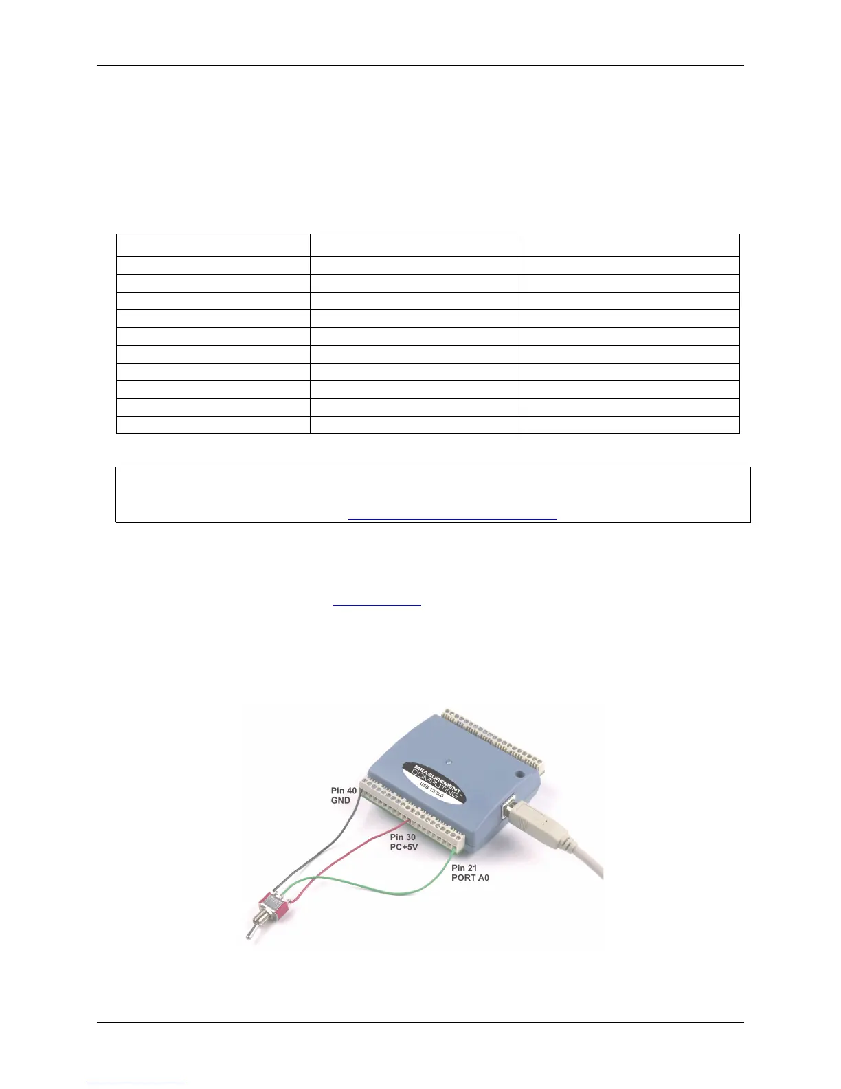
Digital I/O terminals (Port A0 to A7, and Port B0 to B7)
You can connect up to 16 digital I/O lines to the screw terminal containing pins 21 to 40 (Port A0 to Port A7,
and
Port B0 to Port B7.) Refer to the pinout diagrams on page 3-4 for the location of these pins. You can
configure each digital port for either input or output.
When you configure the digital bits for input, you can use the digital I/O terminals to detect the state of any
TTL level input. Refer to the switch shown in Figure and the schematic shown in . If the switch is
set to the +5 V input, Port A0 reads TRUE (1). If you move the switch to GND, Port A0 reads FALSE.
3-8
Figure 3-8. Digital connection Port A0 detecting the state of a switch
Figure 3-9
3-7